Test system and test method for imaging delay time of medium-wave infrared detector

An infrared detector and delay time technology, applied in the field of image processing, can solve the problem of low delay time accuracy, and achieve the effects of improving test accuracy, good scalability, and strong environmental adaptability

Active Publication Date: 2019-08-16
NANJING UNIV OF AERONAUTICS & ASTRONAUTICS
View PDF11 Cites 0 Cited by
  • Summary
  • Abstract
  • Description
  • Claims
  • Application Information

AI Technical Summary

Problems solved by technology

[0005] In order to solve the problem of low accuracy of the imaging delay time of the existing mid-wave infrared detector, the present invention provides a method for detecting the imaging delay time of the mid-wave infrared detector with high precision, and realizes the imaging delay time based on a portable computer and an embedded real-time system. Delay time test system, single detection of imaging delay time of mid-wave infrared detectors and multiple statistics to obtain the average value of delay time, high precision, strong environmental adaptability, good readability, portability, and continuous testing with high reliability

Method used


Image

  • Test system and test method for imaging delay time of medium-wave infrared detector
  • Test system and test method for imaging delay time of medium-wave infrared detector
  • Test system and test method for imaging delay time of medium-wave infrared detector

Examples


Embodiment Construction

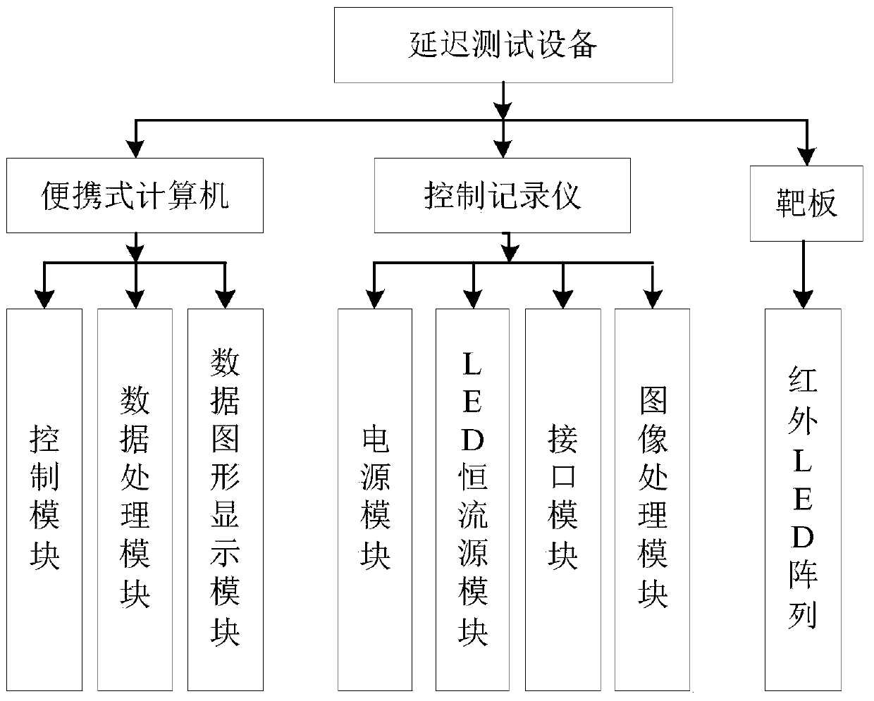
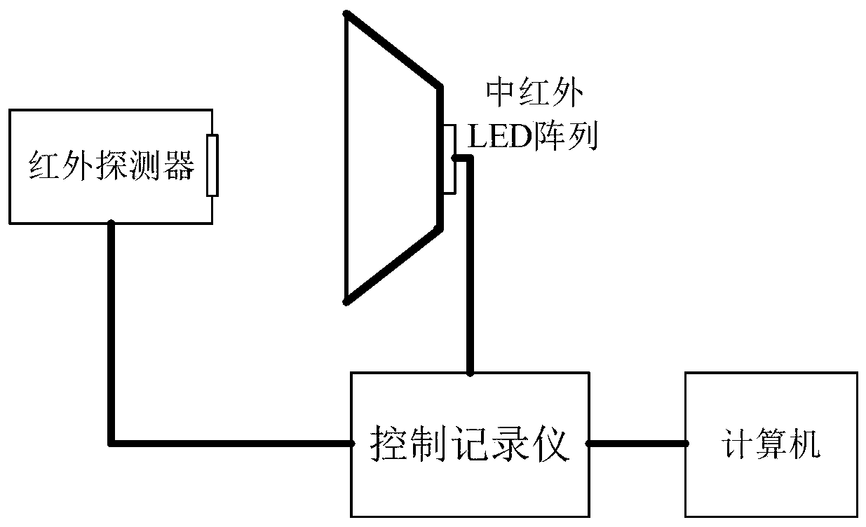
[0054] The present invention will be further described below in conjunction with accompanying drawing. Imaging delay test equipment system structure block diagram of the present invention, as figure 1 , 2 As shown, it includes three parts: target board, control recorder and portable computer.

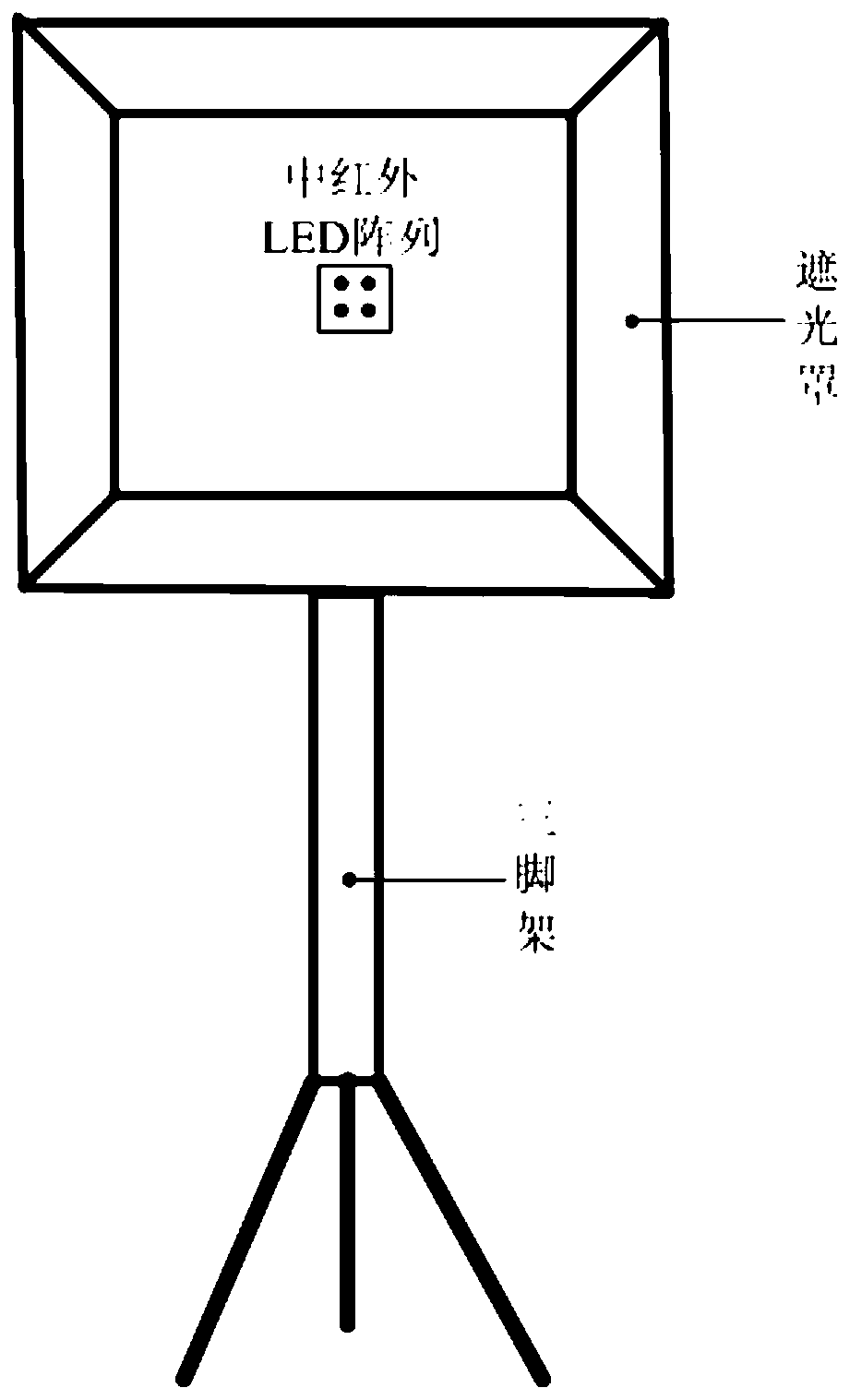
[0055] Such as image 3 As shown, the target board is composed of a target board, a light shield and a tripod. The target board and lens hood are made of aluminum alloy and shaped like a bell-mouthed box. The target board is the bottom of the box, with an array of infrared LEDs installed in the center and a light shield on the edge. The tripod is used to fix the target board and the hood, and the height of the target board can be adjusted during testing.

[0056] Such as Figure 4 As shown, the interior of the control recorder includes four parts: power supply module, image processing module, LED constant current source module, and interface module. The indicator light, the size...


PUM


Abstract

The invention provides a medium wave infrared detector imaging time delay test system and method. The system comprises a portable computer, a control recorder, a target plate (a medium wave infrared LED array) and a medium wave infrared detector, wherein the portable computer is a notebook computer and is connected with the control recorder through the Ethernet cable, a control port of the targetplate and a detector signal output port are connected with the control recorder through special cables. The system is advantaged in that a detector output video signal can be timely acquired, throughhigh-precision control on an LED array work state and real-time processing on acquired images, medium wave infrared detector imaging time delay detection is realized, the detection information is further outputted to the computer to display dynamic imaging time delay change in real time, and high precision, strong environment adaptability and good readability, portability and robustness are realized.

Description

technical field [0001] The invention relates to the technical field of image processing, in particular to a testing system and testing method for imaging delay time of a mid-wave infrared detector. Background technique [0002] Mid-wave infrared detectors are often used in airborne photoelectric systems to detect and track heat source targets. Therefore, the imaging time of infrared detectors directly affects the real-time performance of fighter planes in ground environment reconnaissance and target detection and tracking. The imaging delay time of the mid-wave infrared detector needs to be small enough and within a certain range to ensure the real-time imaging requirements of the reconnaissance image. [0003] By testing the imaging delay time of the medium-wave infrared detector, the quality of the infrared detector is guaranteed to ensure the normal operation of the airborne optoelectronic system. To test the imaging delay time of the medium-wave infrared detector, two c...

Claims


Application Information

Patent Timeline
Patent Type & Authority Patents(China)
IPC IPC(8): G01J5/00
CPCG01J5/00G01J2005/0077
Inventor 闫钧华张寅段贺姜惠华杨勇蔡旭阳黄伟杜君白雪含
Owner NANJING UNIV OF AERONAUTICS & ASTRONAUTICS
Why Eureka
Try Eureka