Plate grid corrosion test method at high temperature and apparatus therefor

A technology for corrosion testing and high-temperature environments, applied in measuring devices, weather resistance/light resistance/corrosion resistance, instruments, etc., can solve problems such as long time consumption, high test cost, product scrap loss, etc., to achieve accurate closure and reduce testing cost, the effect of simplifying the testing process

Active Publication Date: 2018-03-02
CHAOWEI POWER CO LTD
View PDF6 Cites 6 Cited by
  • Summary
  • Abstract
  • Description
  • Claims
  • Application Information

AI Technical Summary

Problems solved by technology

The current grid corrosion resistance test method is to take samples from the finished battery and conduct a destructive continuous charge-discharge test, which takes a long time and high cost of testing. It often takes several months to obtain the final result, and directly causes the product to be scrapped and lost.

Method used


Image

  • Plate grid corrosion test method at high temperature and apparatus therefor
  • Plate grid corrosion test method at high temperature and apparatus therefor
  • Plate grid corrosion test method at high temperature and apparatus therefor

Examples


Embodiment 1

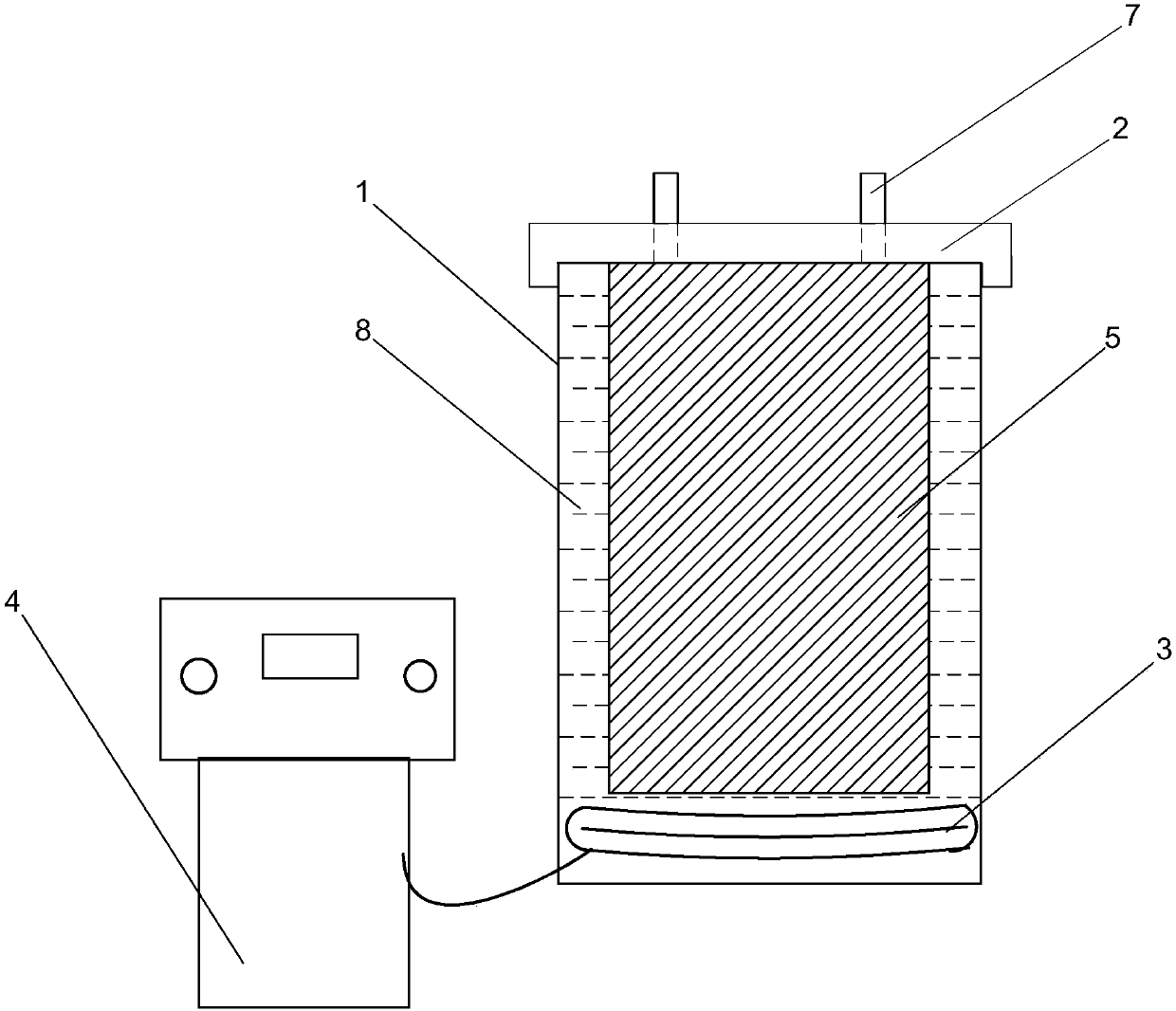
[0033] Such as figure 1 , figure 2 As shown, a high-temperature environment grid corrosion test method includes the following steps:

[0034] A. Make a special high-temperature environment grid corrosion test device;

[0035] B. Select the positive grid and negative grid sample pieces made according to their respective standards, cut out a grid sample piece on each grid, and press it straight. The length of the grid sample piece is 198mm, and the width is 198mm. 98mm, and each grid sample piece retains a tab on the grid;

[0036] C. Use a balance to weigh the grid sample piece in turn, record the weight of the grid sample piece before the corrosion test, and the weighing result is accurate to four decimal places;

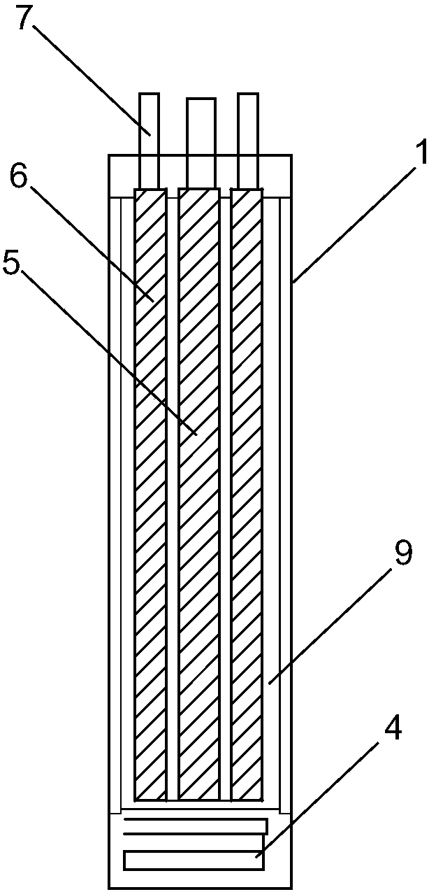
[0037] D. Cover the positive grid sample piece 5 with a single piece of AGM separator of the corresponding specification, and then use the negative grid sample piece 6 to paste and press on both sides of the positive grid sample piece 5 coated by AGM to form...

Embodiment 2

[0046] The length of the grid sample piece is 200mm and the width is 100mm. The density of the colloidal electrolyte used is 1.24g / cm 3 , the electrolyte temperature was 58°C, and the battery was charged with a constant current of 1.8A for 169h. The components of the corrosion film treatment solvent are 3.5% sodium hydroxide, 14% glucose, and the rest are water. There are three pairs of clamping block embedding grooves and reaction tank cover clamping blocks respectively. All the other are with embodiment 1.

Embodiment 3

[0048] The length of the grid sample piece is 202mm, and the width is 102mm. The density of the colloidal electrolyte used is 1.26g / cm 3 , the temperature of the electrolyte is 62°C, and the battery is charged with a constant current of 2.0A for 168h. The components of the corrosion film treatment solvent are 4% sodium hydroxide, 16% glucose, and the rest are water. There are four pairs of clamping block embedding grooves and reaction tank cover clamping blocks respectively. All the other are with embodiment 1.


PUM

PropertyMeasurementUnit
densityaaaaaaaaaa
lengthaaaaaaaaaa
widthaaaaaaaaaa

Abstract

The invention discloses a plate grid corrosion test method at high temperature and an apparatus therefor. In the invention, a more severe corrosion environment of a simulated battery under a working condition is provided, and a plate grid material is subjected to corrosion due to an electrolyte for longer time and at higher intensity, so that the plate grid material can be consumed quicker and theanti-corrosion performance of the plate grid material can be represented quickly, thereby greatly increasing test efficiency on corrosion of the plate grid without consumption of real battery products during the test. The test method only employs a less amount of plate grid material, so that test cost is greatly reduced; meanwhile, by means of a special plate grid corrosion test apparatus at hightemperature for carrying out the plate grid corrosion test at high temperature, temperature control of a colloid electrolyte and accurate sealing of a reaction tank cover are achieved, thereby bringing convenience to the test.

Description

technical field [0001] The invention relates to a method and device for testing battery components, more specifically, it relates to a method and device for testing grid corrosion in a high-temperature environment. Background technique [0002] The grid is an important part of the battery, and its main functions are: as the carrier of the active material, it plays the role of skeleton support and adhesion of the active material; as the conductor of the current, it plays the role of current collection, confluence and transmission; The current sharing of the plate plays the role of evenly distributing the current to the active material. During the use of the battery, once the grid corrosion occurs, the life of the battery is basically terminated. Through the grid corrosion test, the corrosion resistance of the grid can be effectively understood, and it is convenient for technicians to choose a suitable grid for designing or making batteries. The current grid corrosion resist...

Claims


Application Information

Patent Timeline
Patent Type & Authority Applications(China)
IPC IPC(8): G01N17/02
CPCG01N17/02
Inventor 吴鑫陈婷朱军平
Owner CHAOWEI POWER CO LTD
Why Eureka
Try Eureka