A Design Method of Radar Sunny Map with FIR Filter

A design method and filter technology, which can be applied to instruments, radio wave measurement systems, etc., can solve the problems of correct estimation of influence clutter map, strong environmental dependence, and influence clutter map estimation, etc., to achieve convenient design and simple principle. , good real-time effect

Active Publication Date: 2019-09-10
THE 28TH RES INST OF CHINA ELECTRONICS TECH GROUP CORP
View PDF6 Cites 0 Cited by
  • Summary
  • Abstract
  • Description
  • Claims
  • Application Information

AI Technical Summary

Problems solved by technology

[0009] (1) Strong dependence on the environment. When the weather conditions are bad, it is difficult to obtain the radar echo data of clear weather in a short time, and it is impossible to obtain the clear weather map
[0010] (2) The existing clutter map partitions are updated based on signal amplitude fluctuations. When there are point targets in the clutter, it will affect the correct estimation of the clutter map.
[0011] (3) In the existing static ground clutter estimation, if there is communication interference, TV interference, etc., it will affect the clutter map estimation, and the clutter map needs to be corrected

Method used


Image

  • A Design Method of Radar Sunny Map with FIR Filter
  • A Design Method of Radar Sunny Map with FIR Filter
  • A Design Method of Radar Sunny Map with FIR Filter

Examples


Embodiment 1

[0093] The solution of the present invention will be further described in detail below in conjunction with the accompanying drawings.

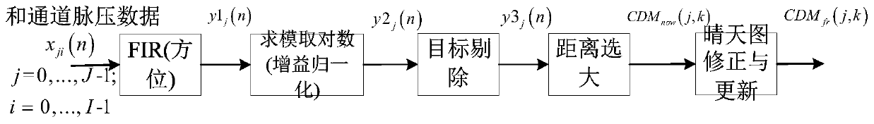
[0094] figure 1 It is the overall processing flow chart. combine figure 1 , the inventive method comprises the following steps:

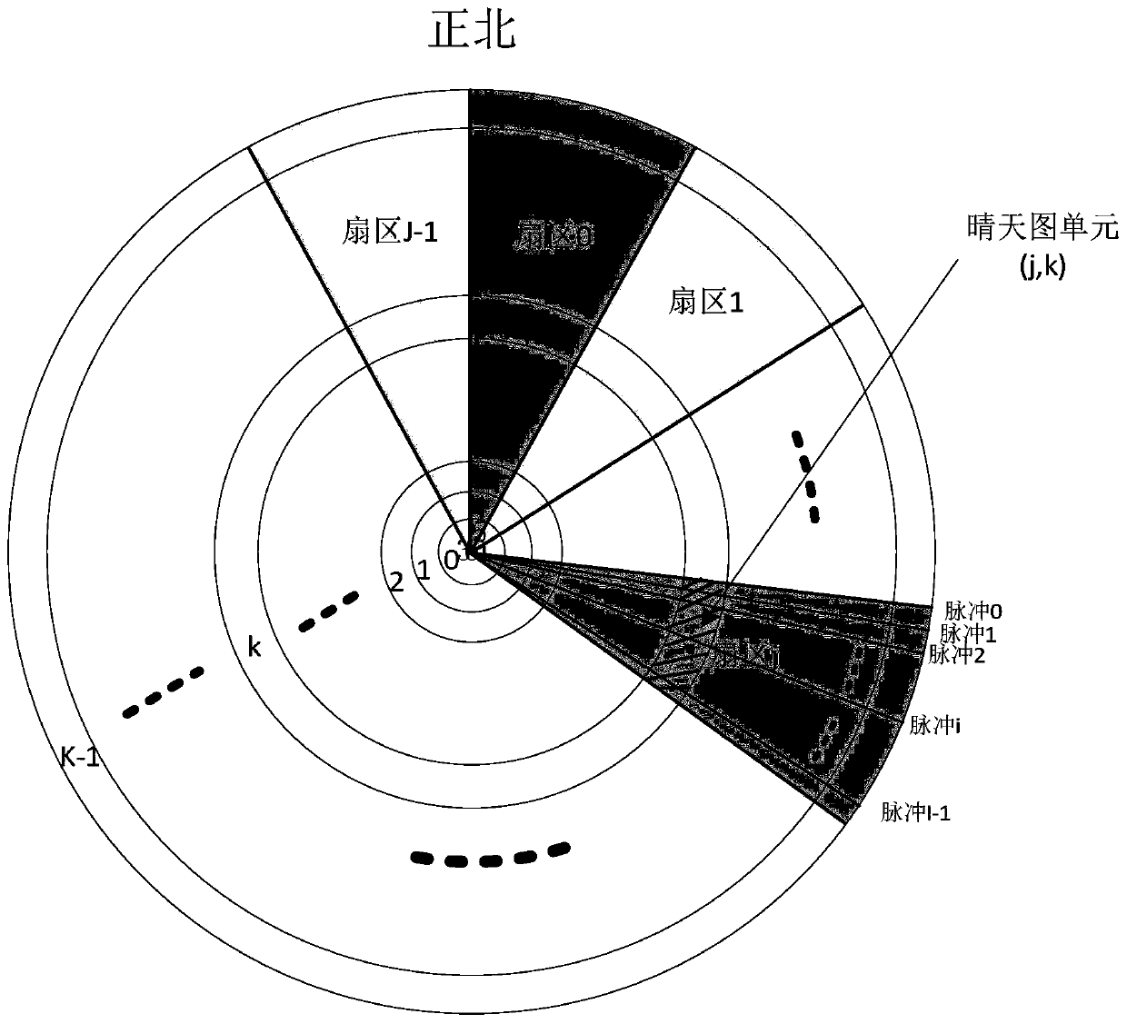
[0095] 1. Calculation of radar parameters: According to the total number of radar range units Rmax and the total number of pulses I in a single sector, calculate the radar clear sky map distance n=Rmax / 2, azimuth resolution unit j=I / 128, and radar noise power estimation NoiseVal. Sector diagram as figure 2 shown.

[0096] 2. FIR processing: adjust the antenna to scan at a low speed, and for the pulse echo data in the jth sector, x ji (n),j=0,...,J-1; i=0,...,I-1,n=0,...,R max The first M (Mj (n)

[0097]

[0098] Wherein, M is an integer less than 1, i is the pulse sequence number in the sector, j is the sector number, n is the distance number, and M is the accumulated pulse number; w i is the filter coe...

Embodiment 2

[0124] 1. Analyze the measured data of XX radar, the radar works in MTD system, the distance resolution unit is 30m, the distance unit is 4000 (total 120km), the antenna scans 6 revolutions per minute, the pulse repetition frequency is 300Hz, and the word length of the collected data is 8 bits (0-255 ). Divide the 360° area of ​​the radar scan into 4096 azimuth units. The distance resolution of the sunny map is 60m, the number of distance units is 2000, the azimuth resolution of the sunny map is 360° / 128, and the radar noise power is estimated to be 20. Radar input echo data such as Figure 4 shown.

[0125] 2. FIR processing: adjust the antenna to scan at a low speed, and for the pulse echo data in the jth sector, x ji (n), j=0,...,127; i=0,...,45, n=0,..., the first 30 scan data in 1999 are processed by FIR to get the sector Filter output signal y1 j (n)

[0126]

[0127] Among them, i is the pulse sequence number in the sector, j is the sector number, n is the distan...


PUM


Abstract

The invention discloses a radar clear day map design method of an FIR filter. According to the method, radar parameter calculation, a radar parameter is calculated according to a work mode and a system parameter of a radar; FIR processing, an antenna is adjusted to a low speed scanning mode, filtering processing of pulse echo is carried out, and ground clutter estimation is calculated; modulo logarithm operation, data is converted into a logarithm which is used for carrying out subsequent target elimination and clutter energy estimation; target elimination, overthreshold processing for sectordata is carried out, and narrow pulse signals of which the number of distance dimensions surpass the threshold are eliminated; distance merging, greatest-selection processing on distance unit data iscarried out to acquire clear day map distance unit data; clear day map correction and update, communication interference influence of a clear day map is eliminated, the clear day map is updated through a clutter map accumulative method, and an accurate clear day map estimate is acquired. The method is advantaged in that a problem of difficulty in carrying out accurate estimation under the static clutter background in the severe weather is solved, and accurately identifying the radar clutter environment to acquire the radar clear day map under the arbitrary weather conditions is guaranteed.

Description

technical field [0001] The invention relates to a method for designing a radar sky map, in particular to a method for designing a radar sky map with an FIR filter. Background technique [0002] Radar echoes not only include a large amount of target information, but also include ground clutter, sea clutter, weather clutter, interference and other information. When the radar is working, the clutter echo amplitude in the surrounding environment is usually stored in an orderly manner according to the two-dimensional plane of distance and azimuth, so as to establish a clutter map. The clutter map is used to store the background clutter power of each range-azimuth unit, and the estimated values ​​of different scanning periods are iteratively averaged to calculate the clutter background estimate. [0003] It is of great significance to carry out the design of the radar clear sky map and establish the radar ground clutter map, estimate the clutter and divide the clutter. The sunny...

Claims


Application Information

Patent Timeline
Patent Type & Authority Patents(China)
IPC IPC(8): G01S7/41
Inventor 龙超胡子军刘子威童建文赵玉丽习云飞李嘉琦欧乐庆王寿峰赵春光翟海涛
Owner THE 28TH RES INST OF CHINA ELECTRONICS TECH GROUP CORP
Why Eureka
Try Eureka