Unloading head, automatic bowl loading machine with unloading head and bowl loading method

A material head and blanking technology, applied in the field of automatic bowl filling machine and its bowl filling, can solve the problems of large space occupation, complex equipment structure, high cost, etc., achieve small material accumulation height, less material accumulation, and improve flatness Effect

Active Publication Date: 2018-03-06
HUNAN JINLU TECH CO LTD
View PDF9 Cites 2 Cited by
  • Summary
  • Abstract
  • Description
  • Claims
  • Application Information

AI Technical Summary

Problems solved by technology

However, for materials with bulk density requirements, using a vibrator or a flattening mechanism for leveling will squeeze out the air between the powder materials and increase the density of the materials, which cannot meet the product quality control requirements, and for materials with poor fluidity, vibration and shaking It is also difficult to achieve the flatness requirements of the material surface
At the same time, the existing bowl filling machine is divided into two processes for filling the material and leveling the surface, which has the problems of low efficiency, complex equipment structure, large space occupation, difficult debugging, and high cost.
In addition, in order to control the amount of bowl filling, the existing bowl filling equipment uses a feeding device to directly add materials into the sagger in the form of falling, and weighs through the weighing component carrying the sagger to control the amount of bowl filling. To ensure the accuracy of weighing, it is necessary to control the feeding speed of the material, and it is necessary to fix the sagger in place before feeding and weighing, which will greatly affect the efficiency of filling the bowl

Method used


Image

  • Unloading head, automatic bowl loading machine with unloading head and bowl loading method
  • Unloading head, automatic bowl loading machine with unloading head and bowl loading method
  • Unloading head, automatic bowl loading machine with unloading head and bowl loading method

Examples


Embodiment Construction

[0028] The present invention will be described in further detail below in conjunction with the accompanying drawings and specific embodiments.

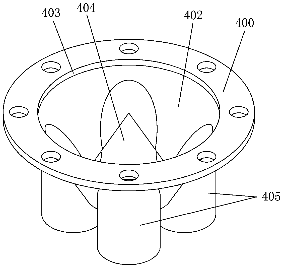
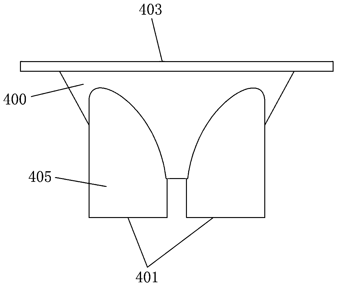
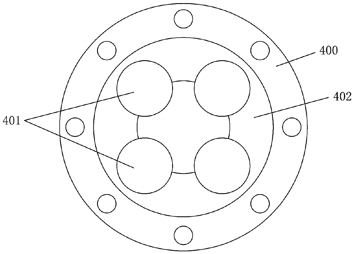
[0029] Such as Figure 1 to Figure 4As shown, the blanking head of this embodiment includes a blanking head body 400, the blanking head body 400 has a material guide cavity 402 and a feed port 403 communicated with the material guide cavity 402, and one end of the blanking head body 400 has several The discharge port 401 for outputting materials communicated with the material guide cavity 402, all the discharge ports 401 are located on the same fixed plane on the blanking head body 400, and several discharge ports 401 are evenly spaced around a fixed axis perpendicular to the fixed plane. Arranged at intervals, the material guide chamber 402 is provided with a material guide cone 404 for guiding the material in the material guide chamber 402 to each outlet 401. The axis of the material guide cone 404 coincides with the fixed axis, and...


PUM


Abstract

The invention discloses an unloading head, an automatic bowl loading machine with the unloading head and a bowl loading method. The unloading head comprises an unloading head body; the unloading headbody is provided with a guide cavity and a feed port communicating with the guide cavity; multiple discharge ports communicating with the guide cavity are formed in one end of the unloading head body;all the discharge ports are positioned on the same fixed plane on the unloading head body; the multiple discharge ports are uniformly arranged at intervals around a fixed axis perpendicular to the fixed plane; a guide cone for guiding materials into each discharge port is arranged in the guide cavity; and the axis of the guide cone is overlapped with the fixed axis. The automatic bowl loading machine comprises an unloading device, a fixing device, and a loading conveying line driven by a three-dimensional space displacement driving device; and the unloading device adopts the unloading head. The bowl loading method is to use the automatic bowl loading machine for enabling the unloading head to extend into a sagger for unloading and leveling at the same time. The unloading head, the automatic bowl loading machine with the unloading head and the bowl loading method have such advantages as uniform discharge and facilitation of improving the bowl loading efficiency and the bowl loading quality.

Description

technical field [0001] The invention relates to the technical field of powder bowl filling equipment, in particular to a feeding head, an automatic bowl filling machine with the feeding head and a bowl filling method thereof. Background technique [0002] In the process of producing powder materials such as cathode materials for lithium-ion batteries, the materials to be sintered must first be loaded into a sagger, and then sintered at a high temperature in a kiln. In order to ensure the consistency of the material after sintering, it is necessary to precisely control the amount of bowl, the loose density of the material in the bowl, and the flatness of the surface of the material in the sagger. [0003] The existing bowl filling equipment all adopts a vibrator or a flattening mechanism to keep the surface of the material in the sagger smooth. However, for materials with bulk density requirements, using a vibrator or a flattening mechanism for leveling will squeeze out the ...

Claims


Application Information

Patent Timeline
Patent Type & Authority Applications(China)
IPC IPC(8): B65B37/02B65B37/18B65B43/52
CPCB65B37/02B65B37/18B65B43/52Y02E60/10
Inventor 欧阳建梅志坤胡忠红胡茂黄映红
Owner HUNAN JINLU TECH CO LTD
Why Eureka
Try Eureka