Biomass gas generating furnace
A coal gasifier and biomass technology, applied in the gasification process, the manufacture of combustible gas, the petroleum industry, etc., can solve the problems of insufficient combustion, low thermal efficiency, waste of straw, etc., to prevent heat loss, high conversion efficiency, The effect of convenient transportation
- Summary
- Abstract
- Description
- Claims
- Application Information
AI Technical Summary
Problems solved by technology
Method used
Image
Examples
Embodiment 1
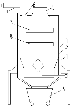
[0027] A heat insulation layer 3 is provided between the furnace shell 1 and the inner shell 2. The bottom of the furnace shell 1 is set as a conical ash outlet, and a conical ash collection tray 4 is provided under the ash outlet. The legs of the ash collection tray 4 A scroll wheel is installed, the scroll wheel is a universal wheel, the top of the furnace shell 1 is provided with a feed inlet 5 and a gas outlet 6, and the inner shell 2 is provided with an upper grate 7 and a lower grate 8, and the upper grate 7 is located on The upper part of the lower fire grate 8;
[0028] The feed inlet 5 is set at the center position of the upper part of the upper grate 7, and the lower part of the feed inlet 5 extends into the inner shell 2; the gas outlet 6 is equipped with a delivery pipe, and a heat exchange device 9 is installed on the outside of the delivery pipe. There is a heat exchange fluid in the device 9, and the heat exchange fluid communicates with the heat exchange device...
Embodiment 2
[0030] A heat insulation layer 3 is provided between the furnace shell 1 and the inner shell 2. The bottom of the furnace shell 1 is set as a conical ash outlet, and a conical ash collection tray 4 is provided under the ash outlet. The legs of the ash collection tray 4 A scroll wheel is installed, the scroll wheel is a universal wheel, the top of the furnace shell 1 is provided with a feed inlet 5 and a gas outlet 6, and the inner shell 2 is provided with an upper grate 7 and a lower grate 8, and the upper grate 7 is located on The upper part of the lower fire grate 8;
[0031] The feed inlet 5 is set at the center position of the upper part of the upper grate 7, and the lower part of the feed inlet 5 extends into the inner shell 2; the gas outlet 6 is equipped with a delivery pipe, and a heat exchange device 9 is installed on the outside of the delivery pipe. There is a heat exchange fluid in the device 9, and the heat exchange fluid communicates with the heat exchange device...
Embodiment 3
[0033] A heat insulation layer 3 is provided between the furnace shell 1 and the inner shell 2. The bottom of the furnace shell 1 is set as a conical ash outlet, and a conical ash collection tray 4 is provided under the ash outlet. The legs of the ash collection tray 4 A scroll wheel is installed, the scroll wheel is a universal wheel, the top of the furnace shell 1 is provided with a feed inlet 5 and a gas outlet 6, and the inner shell 2 is provided with an upper grate 7 and a lower grate 8, and the upper grate 7 is located on The upper part of the lower fire grate 8;
[0034] The feed inlet 5 is set at the center position of the upper part of the upper grate 7, and the lower part of the feed inlet 5 extends into the inner shell 2; the gas outlet 6 is equipped with a delivery pipe, and a heat exchange device 9 is installed on the outside of the delivery pipe. There is a heat exchange fluid in the device 9, and the heat exchange fluid communicates with the heat exchange device...
PUM
| Property | Measurement | Unit |
|---|---|---|
| Thickness | aaaaa | aaaaa |
| Thickness | aaaaa | aaaaa |
Abstract
Description
Claims
Application Information
 - R&D
- Intellectual Property
- Life Sciences
- Materials
- Tech Scout
- Unparalleled Data Quality
- Higher Quality Content
- 60% Fewer Hallucinations
Browse by: Latest US Patents, China's latest patents, Technical Efficacy Thesaurus, Application Domain, Technology Topic, Popular Technical Reports.
© 2025 PatSnap. All rights reserved.Legal|Privacy policy|Modern Slavery Act Transparency Statement|Sitemap|About US| Contact US: help@patsnap.com

