
Efficient coal catalytic gasification device and method for producing methane-rich synthesis gas

A technology of coal catalytic gasification and methane synthesis gas, which is applied in gasification process, granular/powdered fuel gasification, and combustible gas production, etc. It can solve the problems of low carbon conversion rate and gasification intensity, poor operation stability, and methane yield Low-level problems, to achieve the effect of improving carbon conversion rate, reducing load, and high methane production rate

Active Publication Date: 2020-10-16
CHINA PETROLEUM & CHEM CORP +1
View PDF5 Cites 0 Cited by
  • Summary
  • Abstract
  • Description
  • Claims
  • Application Information

AI Technical Summary

Problems solved by technology

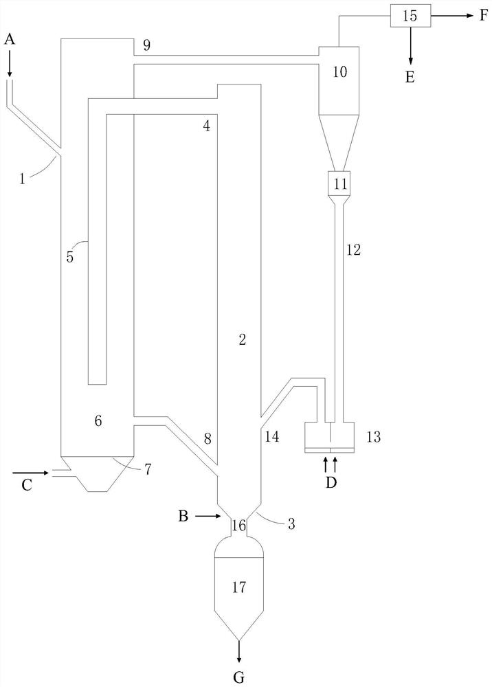
[0008] One of the technical problems mainly solved by the present invention is the problems of low carbon conversion rate and gasification intensity, low methane yield, high energy consumption and poor operation stability in the prior art. The present invention proposes a high-efficiency coal catalytic gas A device for producing methane-enriched syngas. The device is composed of a fluidized bed gasifier and a fluidized bed pyrolysis methanation furnace. Pyrolysis semi-coke, circulating semi-coke particles and gasification agent are fed into the fluidized bed gasification furnace , carry out high-temperature combustion and gasification reaction, generate high-temperature syngas and enter the pyrolysis methanation furnace through the pipe, and the load contains CO 2 Under the action of the catalyst of trapping and mineral binding substances, low-temperature pyrolysis and methanation reactions are carried out to generate methane-rich synthesis gas

Method used


Image

  • Efficient coal catalytic gasification device and method for producing methane-rich synthesis gas
  • Efficient coal catalytic gasification device and method for producing methane-rich synthesis gas
  • Efficient coal catalytic gasification device and method for producing methane-rich synthesis gas

Examples


Embodiment 1

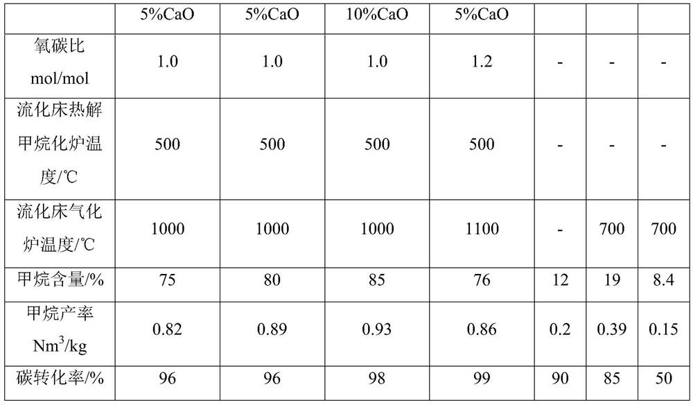
[0042] A high-efficiency coal catalytic gasification device for producing methane-rich synthesis gas. The inner diameter of the fluidized bed pyrolysis methanation furnace is 1.0m, the height is 12m, and the height of the raw material inlet is located at 2 / 3 of the height of the fluidized bed pyrolysis methanation furnace. The inner diameter of the fluidized bed gasifier is 0.8m, and the height is 15m. The semi-coke inlet is located at 1 / 8 of the height of the fluidized bed gasifier, and the return inlet is located at 1 / 4 of the height of the fluidized bed gasifier. The length of the bed pyrolysis methanation furnace is 9m, accounting for 3 / 4 of the height of the methanation furnace.

[0043] In the experiment, Inner Mongolia lignite and 10% K 2 CO 3 +5% CaO catalyst mixed, put into the fluidized bed pyrolysis methanation furnace from the raw material inlet, nitrogen gas is passed into the fluidizing air gas distributor to make the raw material turbulent and fluidized in the ...

Embodiment 2

[0045] A high-efficiency coal catalytic gasification device for producing methane-rich synthesis gas. The inner diameter of the fluidized bed pyrolysis methanation furnace is 1.0m, the height is 12m, and the height of the raw material inlet is located at 2 / 3 of the height of the fluidized bed pyrolysis methanation furnace. The inner diameter of the fluidized bed gasifier is 0.8m, and the height is 15m. The semi-coke inlet is located at 1 / 8 of the height of the fluidized bed gasifier, and the return inlet is located at 1 / 4 of the height of the fluidized bed gasifier. The length of the bed pyrolysis methanation furnace is 10m, accounting for 5 / 6 of the height of the methanation furnace.

[0046] In the experiment, Inner Mongolia lignite and 10% K 2 CO 3 +5% CaO catalyst mixed, put into the fluidized bed pyrolysis methanation furnace from the raw material inlet, nitrogen gas is passed into the fluidizing air gas distributor to make the raw material turbulent and fluidized in the...

Embodiment 3

[0048] A high-efficiency coal catalytic gasification device for producing methane-rich synthesis gas. The inner diameter of the fluidized bed pyrolysis methanation furnace is 1.0m, the height is 12m, and the height of the raw material inlet is located at 2 / 3 of the height of the fluidized bed pyrolysis methanation furnace. The inner diameter of the fluidized bed gasifier is 0.8m, and the height is 15m. The semi-coke inlet is located at 1 / 8 of the height of the fluidized bed gasifier, and the return inlet is located at 1 / 4 of the height of the fluidized bed gasifier. The length of the bed pyrolysis methanation furnace is 9m, accounting for 3 / 4 of the height of the methanation furnace.

[0049] In the experiment, Inner Mongolia lignite and 10% K 2 CO 3 +10%CaO catalyst mixed, put into the fluidized bed pyrolysis methanation furnace from the raw material inlet, nitrogen gas is passed into the fluidized air gas distributor to make the raw material turbulent and fluidized in the f...


PUM

PropertyMeasurementUnit
particle diameteraaaaaaaaaa

Abstract

The invention relates to an apparatus and a method for producing methane-rich synthesis gas through efficient coal catalytic gasification. A purpose of the present invention is to solve the problems of low carbon conversion rate, low gasification intensity, low methane yield, high energy consumption and poor gasification furnace operation stability in the prior art. The apparatus comprises a fluidized bed gasification furnace and a fluidized bed pyrolysis methanation furnace, wherein a raw material inlet is positioned on the upper portion of the fluidized bed pyrolysis methanation furnace, thebottom portion of the fluidized bed pyrolysis methanation furnace is connected to the bottom portion of the fluidized bed gasification furnace, and a synthesis gas conduction pipe connected to the outlet above the fluidized bed gasification furnace extends into the bottom portion of the pyrolysis methanation furnace. The method mainly comprises that a catalyst-loading coal sample and high-temperature synthesis gas are subjected to a catalytic pyrolysis and methanation reaction in the fluidized bed pyrolysis methanation furnace, the semi-coke particles obtained after the pyrolysis and fly ashparticles enter the fluidized bed gasification furnace, and a combustion gasification reaction is performed. With the technical scheme of the present invention, the problems in the prior art are wellsolved. The apparatus and the method of the present invention can be used for the coal-to-methane-rich synthesis gas field.

Description

technical field [0001] The present invention relates to a high-efficiency coal catalytic gasification device and method, more specifically, the present invention designs a catalytic gasification reaction combining a staged reaction fluidized bed pyrolysis methanation furnace and a fluidized bed gasification furnace The device and method belong to the field of coal catalytic gasification. Background technique [0002] Rich coal, poor oil, and little gas are the characteristics of my country's energy structure. With the rapid development of my country's economy and the acceleration of urbanization, the demand for natural gas is increasing. my country's own natural gas production cannot meet the demand for natural gas, and the contradiction between supply and demand has become increasingly prominent. The supply gap can only be made up by relying on imports, which has greatly affected my country's energy security. In view of the fact that my country is a large coal country with...

Claims


Application Information

Patent Timeline
Patent Type & Authority Patents(China)
IPC IPC(8): C10J3/54C10J3/56C10J3/58C10J3/84
CPCC10J3/54C10J3/56C10J3/58C10J3/84C10J2300/093C10J2300/0986C10J2300/1662C10J2300/1807Y02P20/52
Inventor 金渭龙顾松园钟思青高攀
Owner CHINA PETROLEUM & CHEM CORP
Learn More