Electroplating equipment and electroplating method

A technology of electroplating equipment and electroplating tanks, applied in the direction of electrodes, etc., can solve the problems of low current density, affecting the quality of electroplating, high current density, etc., and achieve the effect of improving uniformity, improving electroplating quality, and uniform density distribution

Inactive Publication Date: 2018-03-06
GUANGDONG CHAMPION ASIA ELECTRONICS CO LTD
View PDF3 Cites 2 Cited by
  • Summary
  • Abstract
  • Description
  • Claims
  • Application Information

AI Technical Summary

Problems solved by technology

However, since the current of the circuit board is introduced through the conductive pinch of the hanger, the current density of the two edge areas of the circuit board to be plated close to the conductive pinch is relatively high, while the current density of the central area of ​​the circuit board far away from the conductive pinch is relatively high. lower current density
Moreover, since the deposition amount of metal ions is proportional to the current density, the metal deposited on the two edge areas connected to the circuit board and the conductive pinch is relatively thick, while the metal deposited on the central area of ​​the circuit board is relatively thin, resulting in the unevenness of metal deposition. Uneven thickness affects the quality of electroplating

Method used


Image

  • Electroplating equipment and electroplating method

Examples


Embodiment Construction

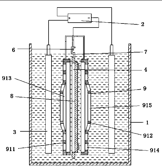
[0015] Such as figure 1 As shown in , a kind of electroplating equipment provided by an embodiment of the present invention includes electroplating tank 1, power supply device 2, anode rod 3, electroplating anode 5, cathode rod 4 and hanger 6, one end of said cathode rod 4 and anode One end of the rod 3 is respectively connected to the positive pole and the negative pole of the power supply device 2, the cathode rod 4 and the anode rod 3 are arranged opposite to the two sides of the hanger 6, the hanger 6 has a plurality of conductive pinches 7, the electroplating The equipment also includes an auxiliary cathode rod 8 and an auxiliary cathode cover 9 , the auxiliary cathode rod 8 is connected to the negative pole of the power supply device 2 , and the auxiliary cathode cover 9 is fixedly connected to the auxiliary cathode rod 8 .

[0016] Further, the auxiliary cathode cover 9 is arranged between the hanger 6 and the electroplating anode 5 .

[0017] Further, the auxiliary ca...


PUM


Abstract

The invention relates to electroplating equipment. The electroplating equipment comprises an electroplating tank, a power supply device, an anode bar, an electroplating anode, a cathode bar and a hanging frame, wherein one end of the cathode bar and one end of the anode bar are respectively connected with the anode and the cathode of the power supply device, the cathode bar and the anode bar are oppositely arranged at the two sides of the hanging frame, the hanging frame is provided with multiple conductive pinch points, the electroplating equipment also comprises an auxiliary cathode bar andan auxiliary cathode cover, the auxiliary cathode bar is connected with the cathode of the power supply device, and the auxiliary cathode cover is fixedly connected with the auxiliary cathode rod. Compared with the prior art, the electroplating equipment and the electroplating method in the technical scheme have the advantages that the auxiliary cathode cover can be utilized for controlling the quantity of metal ions passing through a first through hole and a second through hole, so that the density distribution of the metal ions after passing through the auxiliary cathode cover is more uniform, and the thickness uniformity of a metal layer deposited on a circuit board is improved, so that the electroplating quality of the circuit board is improved.

Description

technical field [0001] The invention relates to the field of electroplating processing, in particular to an electroplating equipment and an electroplating method. Background technique [0002] With the rapid development of the electronic industry, the manufacturing technology of circuit boards, which are the basic components of electronic products, is becoming more and more important. Circuit boards are generally made of copper-clad substrates through a series of processes such as cutting, drilling, electroplating, exposure, development, etching, lamination, printing, and molding. For details, please refer to the article "Dielectric characterization of printed circuitboard substrates" published by C.H.Steer et al. in Proceedings of the IEEE, Vol.39, No.2 (August 2002). [0003] Among them, electroplating is an important manufacturing process of circuit board production, which mainly uses electroplating equipment to selectively plate copper on the surface of the circuit bo...

Claims


Application Information

Patent Timeline
Patent Type & Authority Applications(China)
IPC IPC(8): C25D17/12
CPCC25D17/12
Inventor 刘继承汪小青李强
Owner GUANGDONG CHAMPION ASIA ELECTRONICS CO LTD
Why Eureka
Try Eureka