A Vertical Tube Falling Film Evaporator
A falling film evaporator and standpipe technology, applied in standpipe evaporators, evaporator accessories, evaporation, etc., can solve the problems of low heat exchange efficiency of falling film evaporators, reduce temperature, reduce thermal deterioration, and reduce overheating Effect
- Summary
- Abstract
- Description
- Claims
- Application Information
AI Technical Summary
Problems solved by technology
Method used
Image
Examples
Embodiment 1
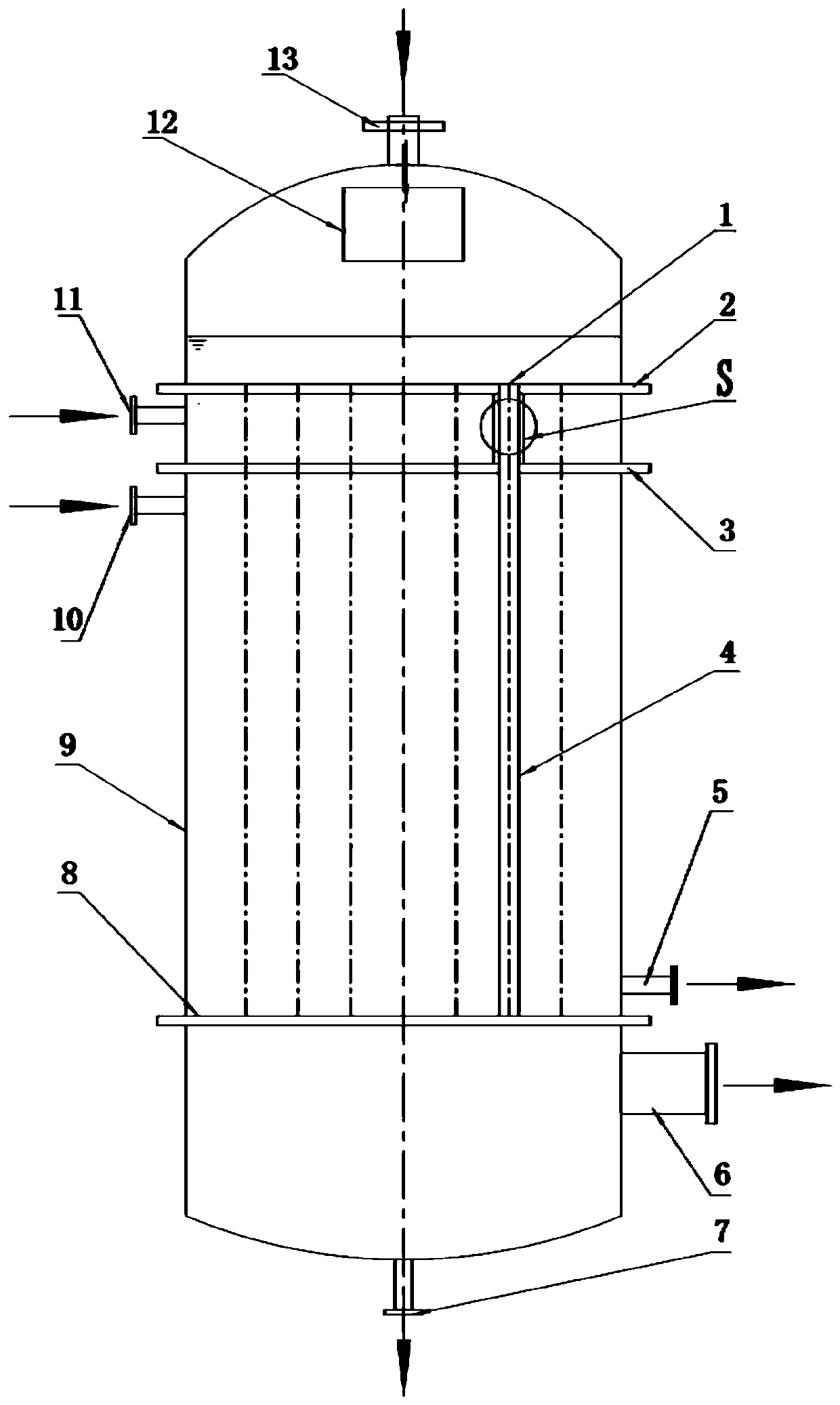
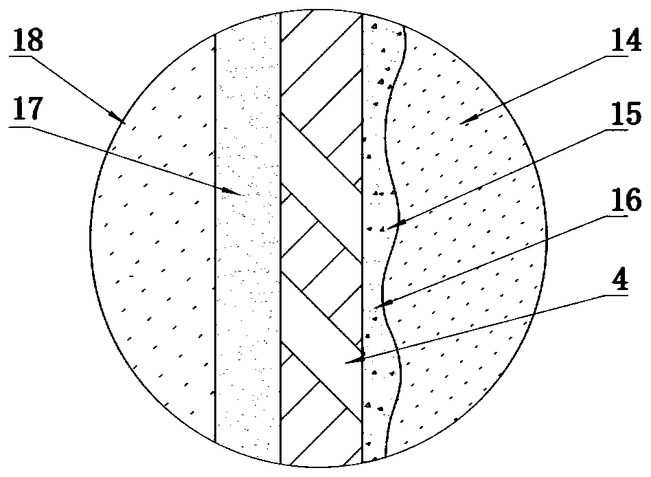
[0033] Such as figure 1 As shown, a vertical tube falling film evaporator provided in this embodiment includes a housing 9, and the interior of the housing 9 is divided into a feed chamber, a carrier gas chamber, a heating chamber, and a gas-liquid separation chamber from top to bottom; A liquid distributor 12 is provided in the cavity, and a liquid distributor 1 is provided at the bottom of the feeding chamber; several evaporation tubes 4 are vertically provided in the housing 9, one end of the evaporation tube 4 is connected to the liquid distributor 1, and the other end passes through the carrier gas chamber After connecting with the heating chamber, the gas-liquid separation chamber is connected; the carrier gas chamber is filled with non-condensable gas 18, and the non-condensable gas 18 enters the interior through the side wall of the evaporation tube 4.
[0034] In this embodiment, an upper tube sheet 2, a middle tube sheet 3 and a lower tube sheet 8 are arranged horizo...
Embodiment 2
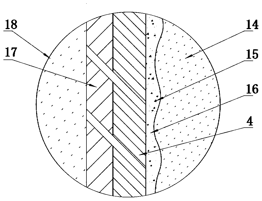
[0042] A vertical tube falling film evaporator provided in this embodiment has the same principle as that of Embodiment 1, and its structure is similar to that of Embodiment 1. The only difference is that: image 3 As shown, the material of the sleeve 17 includes metal pipe, plexiglass or resin, and other processable inelastic materials that can withstand a temperature of 150° other than the materials listed in this embodiment. In this embodiment, the sleeve 17 The material is preferably a metal pipe. A through hole is provided on the side wall of the metal tube, and the through hole is set in one-to-one correspondence with the air inlet to ensure that the non-condensable gas 18 can pass through the casing 17 and enter the evaporation tube 4 .
[0043] Further, the diameter of the aforementioned through hole is 0.1 mm-5 mm, the thickness of the side wall of the evaporation tube 4 is 1 mm-35 mm, and the thickness of the side wall of the sleeve 17 is 1 mm-50 mm. Preferably, the...
PUM
| Property | Measurement | Unit |
|---|---|---|
| pore size | aaaaa | aaaaa |
| thickness | aaaaa | aaaaa |
| diameter | aaaaa | aaaaa |
Abstract
Description
Claims
Application Information
 - R&D
- Intellectual Property
- Life Sciences
- Materials
- Tech Scout
- Unparalleled Data Quality
- Higher Quality Content
- 60% Fewer Hallucinations
Browse by: Latest US Patents, China's latest patents, Technical Efficacy Thesaurus, Application Domain, Technology Topic, Popular Technical Reports.
© 2025 PatSnap. All rights reserved.Legal|Privacy policy|Modern Slavery Act Transparency Statement|Sitemap|About US| Contact US: help@patsnap.com


