

Hydraulic locking mechanism for oil storage tank of oil tank truck
A locking mechanism and oil storage tank technology, which is applied to oil tankers, motor vehicles, goods transport vehicles, etc., can solve the problems of insufficient safety and shock absorption of the locking mechanism, reducing the practicability of the locking mechanism, and the return of lubricating oil. , to enhance the installation stability, reduce wear and tear, and avoid the effect of backflow
- Summary
- Abstract
- Description
- Claims
- Application Information
AI Technical Summary
Problems solved by technology
Method used
Image

Examples
Embodiment Construction
[0021] The following will clearly and completely describe the technical solutions in the embodiments of the present invention with reference to the accompanying drawings in the embodiments of the present invention. Obviously, the described embodiments are only some, not all, embodiments of the present invention.
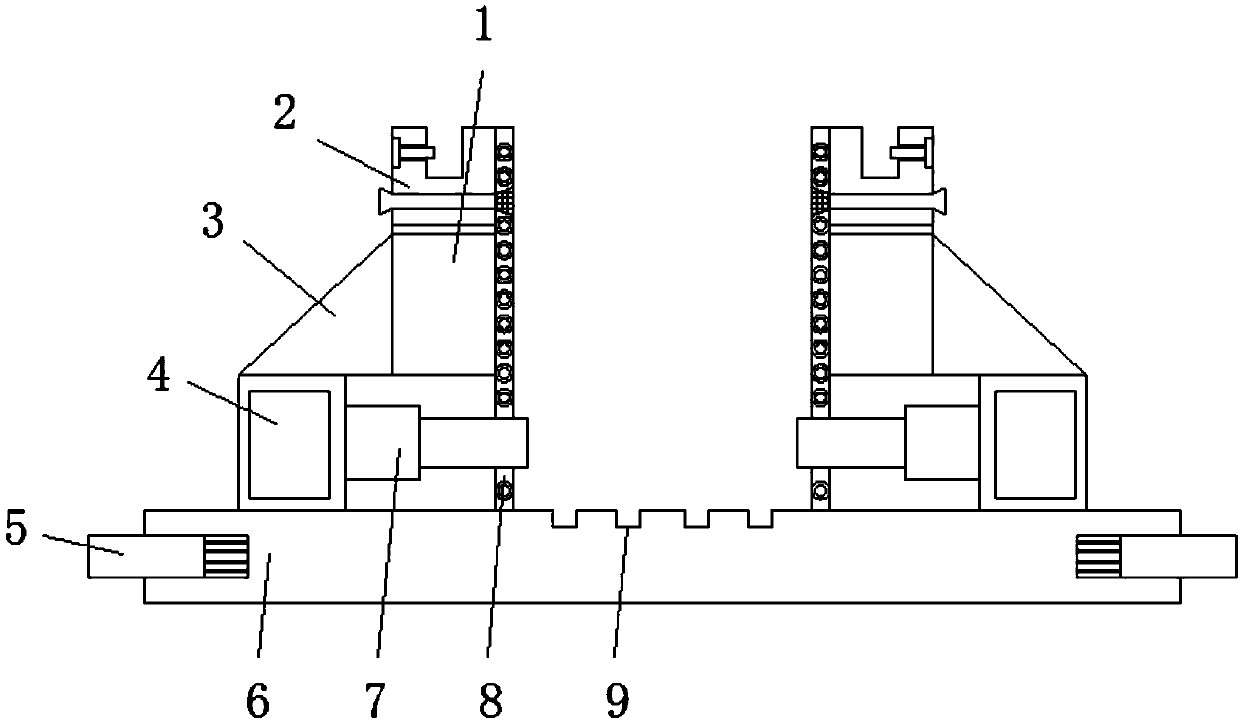
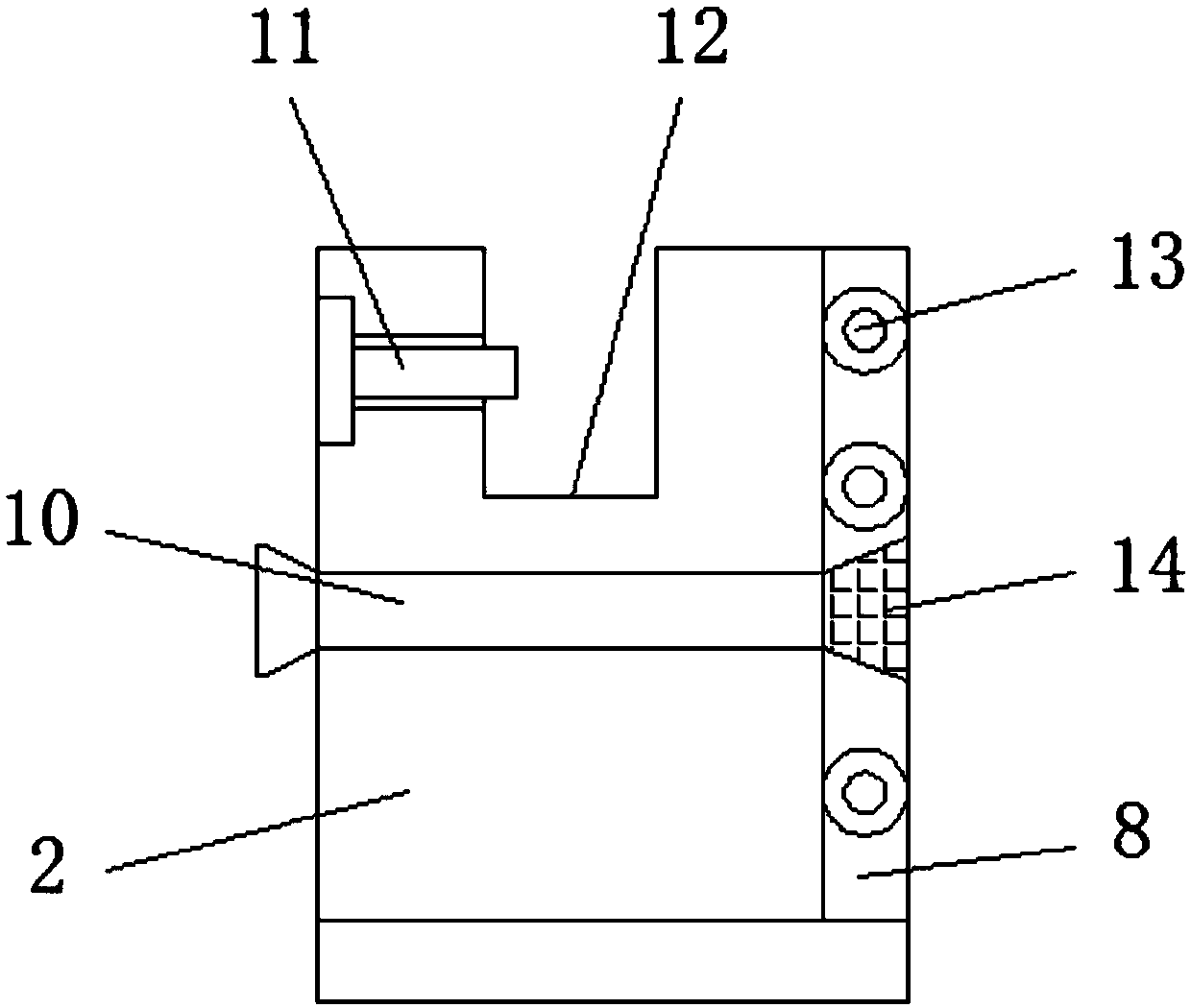
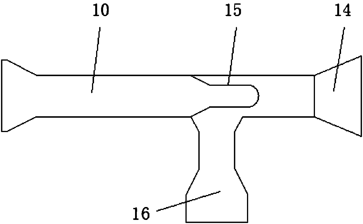
[0022] refer to Figure 1-3 , a hydraulic locking mechanism for an oil storage tank of an oil tanker, comprising a clamping plate 1, a clamping plate 2 is arranged on the top of the clamping plate 1, a clamping groove 12 is opened on the top of the clamping plate 2, and the clamping groove 12 A positioning pin 11 is arranged on one side, an oil guide pipe 10 is arranged inside the clamping plate 2, an oil distribution pipe 15 is arranged inside the oil guide pipe 10, an oil injection nozzle 14 is arranged inside the oil guide pipe 10, and a return chamber 16 is arranged on the top of the oil guide pipe 10. The inner and outer walls of the clamping plate 1 are provide...
PUM
 Abstract
Description
Claims
Application Information