
Buoyancy compensation control method for AUV (autonomous underwater vehicle) in deep submergence motion

A technology for compensating control and buoyancy, applied in motor vehicles, transportation and packaging, ships, etc., can solve the problems of increasing the AUV's fixed-depth sailing resistance, the error between the AUV's sailing depth and the commanded depth, and increasing energy consumption, so as to improve maneuverability and Control accuracy, eliminate trim angle deviation, increase the effect of sailing time

Active Publication Date: 2018-03-09
HARBIN ENG UNIV
View PDF6 Cites 9 Cited by
  • Summary
  • Abstract
  • Description
  • Claims
  • Application Information

AI Technical Summary

Problems solved by technology

However, when the AUV dives into the deep sea area at a large depth, the density, pressure, salinity, and temperature of seawater will change due to the change in depth. These factors will cause an unknown change in the buoyancy of the AUV, and eventually cause gravity. out of balance with buoyancy
[0003] Due to the influence of residual buoyancy, the AUV will have a certain pitch angle when diving in the deep sea area, which will also cause a certain error between the navigation depth of the AUV and the command depth. These effects have strict requirements on the control accuracy of underwater acoustic equipment. very unfavorable
At the same time, the influence of residual buoyancy will also increase the resistance of AUV's depth-fixed navigation, increase energy consumption, and reduce AUV's navigation time.

Method used


Image

  • Buoyancy compensation control method for AUV (autonomous underwater vehicle) in deep submergence motion
  • Buoyancy compensation control method for AUV (autonomous underwater vehicle) in deep submergence motion
  • Buoyancy compensation control method for AUV (autonomous underwater vehicle) in deep submergence motion

Examples


Embodiment Construction

[0021] The following examples describe the present invention in more detail.

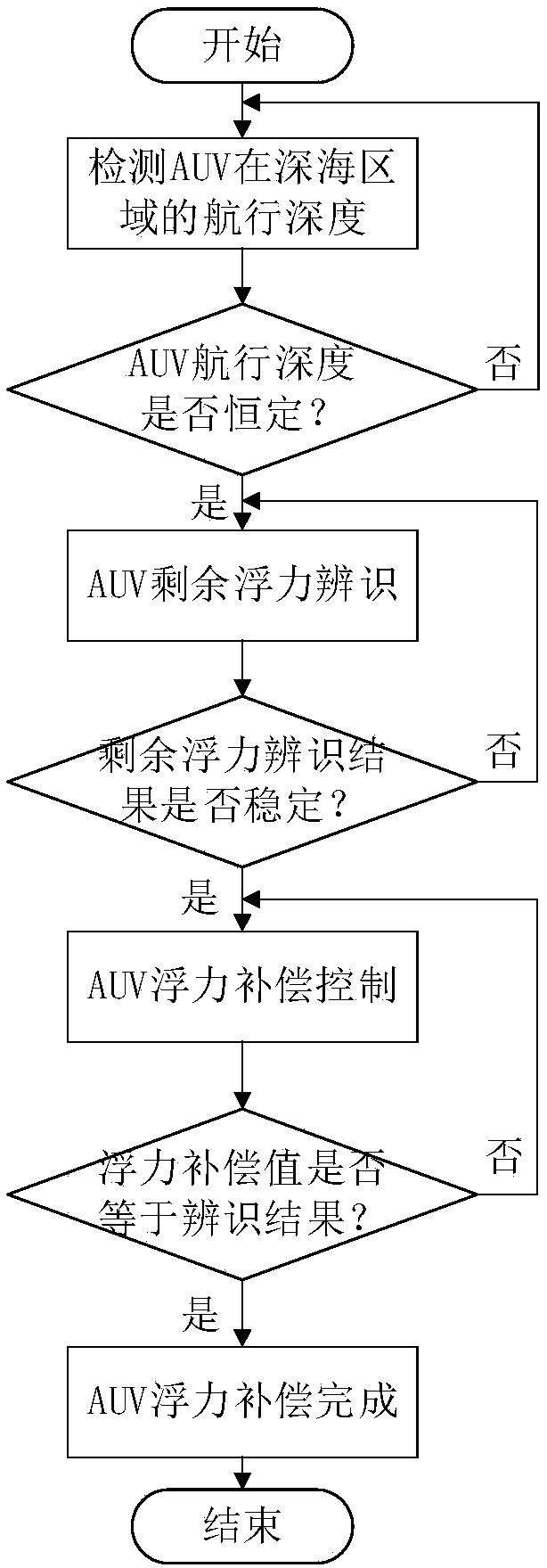
[0022] combine figure 1 , the buoyancy compensation control method of the AUV large submerged deep motion of the present invention mainly includes the following steps:

[0023] Step 1: Use the depth sensor carried by the AUV to detect the depth of the AUV when it is sailing in the deep sea;

[0024] Step 2: When the AUV's navigation depth in the deep sea area is stable, use the AUV residual buoyancy identification algorithm to identify the remaining buoyancy of the AUV when it is sailing at a fixed depth in the current deep sea area;

[0025] Step 3: When the identification result of the AUV residual buoyancy identification algorithm is stable, then perform buoyancy compensation on the AUV through the oil bladder buoyancy equalization system; otherwise, continue to identify the residual buoyancy of the AUV when it sails at a fixed depth in the deep sea area;

[0026] Step 4: When the buoyancy comp...


PUM


Abstract

The invention provides a buoyancy compensation control method for an AUV (autonomous underwater vehicle) in deep submergence motion. The method comprises steps as follows: depth of the AUV during depth-fixed navigation in a deep sea area is detected; residual buoyancy to the AUV during depth-fixed navigation in the current deep sea area is identified with an AUV residual buoyancy identification algorithm; when the identification result is stable, the AUV is subjected to buoyancy compensation by an oil sac type buoyancy balancing system, otherwise, the residual buoyancy to the AUV during depth-fixed navigation in the deep sea area is identified continuously; when a buoyancy identification value of the AUV is equal to a residual buoyancy value identified with the AUV residual buoyancy identification algorithm, buoyancy compensation for the AUV is finished; otherwise, buoyancy compensation for the AUV is continued. According to the buoyancy compensation control method for the AUV in deepsubmergence motion, influence of the residual buoyancy can be effectively balanced, trim angle deviation of the AUV is eliminated, controllabitity and control precision of the AUV are improved, resistance to the AUV during depth-fixed navigation is reduced, and the running time of the AUV is prolonged under the condition of carrying the same energy.

Description

technical field [0001] The invention relates to a control method of an underwater autonomous vehicle, in particular to a buoyancy compensation control method when an AUV performs a large submersible movement. Background technique [0002] Autonomous Underwater Vehicle (AUV) is a mission controller that integrates artificial intelligence and other advanced computing technologies, integrating deep submersibles, sensors, environmental effects, computer software, energy storage, conversion and propulsion, High technologies such as new materials, new processes, and underwater intelligence have broad application prospects. The deep sea area in the ocean accounts for 89% of the total sea area. In order to further understand and develop the ocean, it is necessary to explore the deep sea area with the help of high-precision underwater acoustic equipment carried by AUVs. However, when the AUV dives into the deep sea area at a large depth, the density, pressure, salinity, and temperat...

Claims


Application Information

Patent Timeline
Patent Type & Authority Applications(China)
IPC IPC(8): B63G8/14B63G8/00
CPCB63G8/001B63G8/14B63G2008/004
Inventor 张宏瀚宫利明凡浩许亚杰陈涛周佳加
Owner HARBIN ENG UNIV
Learn More