
Material-saving optimized type cement pile machine

A cement pile, material-saving technology, applied in the direction of sheet pile walls, drilling equipment and methods, construction, etc., can solve the problems of reducing the bearing capacity of ground piles, multiple raw materials, waste, etc., to reduce project cost and promote full refinement , The effect of saving raw materials

Inactive Publication Date: 2018-03-16
丁向峰
View PDF6 Cites 3 Cited by
  • Summary
  • Abstract
  • Description
  • Claims
  • Application Information

AI Technical Summary

Problems solved by technology

[0002] With the development of the urbanization process, high-rise buildings in cities and towns have sprung up like mushrooms after a spring rain; a solid foundation needs to be laid before the construction of the building. For the soft soil layer, the construction team often uses the rotary jet machine to drive the ground piles. , after the cement and soft soil medium solidify, a solid cement mixing pile is formed. The pile body of the cement mixing pile and the soil layer produce a large frictional resistance, which supports the vertical load formed by the building above, so the pile body and the soil layer The contact area directly determines the bearing capacity of the ground pile; the cross-section of the cement mixing pile driven into the construction field is circular at present. Since the circumference of the circle is the smallest under the same area, the cylindrical ground pile The area of ​​the formed pile body is the smallest, and the bearing capacity that can be provided at this time is also the smallest. Therefore, the traditional pile driving and pile formation methods cannot fully utilize the friction force of the soil layer on the pile body, which reduces the bearing capacity of the ground pile and wastes a lot of time. many raw materials

Method used


Image

  • Material-saving optimized type cement pile machine
  • Material-saving optimized type cement pile machine
  • Material-saving optimized type cement pile machine

Examples


Embodiment

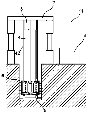
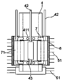
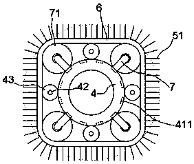
[0019] exist Figure 1 to Figure 3 In the shown embodiment, this material-saving optimized cement pile driver includes a grouting machine 1, a support frame 2, a driving machine 3, a transmission rod 4 and a drill bit 5; the upper end of the transmission rod 4 is detachably installed on the driving machine 3 Above, the drill bit 5 is arranged at the lower end of the transmission rod 4; a grouting port is opened on the drill bit 5; a cutting blade 51 is also arranged on the drill bit 5;

[0020] The transmission rod 4 is a hollow structure, and a guide pipe 11 is interspersed in the hollow area of ​​the transmission rod 4, and one end of the guide pipe 11 is connected with the grouting machine 1, and the other end is communicated with the grouting port on the drill bit 5; The grouting port is equidistantly arranged on the bottom and the side peripheral wall of the drill bit 5, and the spraying direction of the grouting port is parallel to the plane where the adjacent excavation...


PUM


Abstract

The invention relates to a material-saving optimized type cement pile machine. The material-saving optimized type cement pile machine comprises a grouting machine, a supporting frame, a driving machine, a transmission rod and a drill bit; a flow guiding tube is inserted in a hollow area of the transmission rod in a penetrating mode; a reinforcing ring is arranged outside of the transmission rod ina sleeving mode and is connected to the supporting frame through a supporting rod; the transmission rod can freely rotate relative to the reinforcing ring and the supporting rod; fixing grooves are formed in the outer ring surface of the reinforcing ring at equal intervals, and reinforcing rods are mounted in the fixing grooves; transmission wheels are arranged on the reinforcing rods in a sleeving mode, forming tracks are further arranged outside of the transmission rods and the reinforcing rings in a sleeving mode, and cutting blades are arrayed on the outer circumferences of the forming tracks at equal intervals; and the transmission wheels are correspondingly engaged with the forming tracks and the transmission rods through gears. According to the material-saving optimized type cementpile machine, piling and pile forming can be quick and convenient, the friction area generated between a ground pile and a soil layer is great, the bearing capacity of a single pile is effectively improved, raw materials can be saved, and the construction cost is reduced.

Description

technical field [0001] The invention relates to a building construction tool, in particular, a pile driver. Background technique [0002] With the development of the urbanization process, high-rise buildings in cities and towns have sprung up like mushrooms after a spring rain; a solid foundation needs to be laid before the construction of the building. For the soft soil layer, the construction team often uses the rotary jet machine to drive the ground piles. , after the cement and soft soil medium solidify, a solid cement mixing pile is formed. The pile body of the cement mixing pile and the soil layer produce a large frictional resistance, which supports the vertical load formed by the building above, so the pile body and the soil layer The contact area directly determines the bearing capacity of the ground pile; the cross-section of the cement mixing pile driven into the construction field is circular at present. Since the circumference of the circle is the smallest under...

Claims


Application Information

Patent Timeline
IPC IPC(8): E21B7/00E21B12/00E21B17/00E21B10/60E02D5/46
CPCE21B7/00E02D5/46E21B10/60E21B12/00E21B17/00
Inventor 丁向峰
Owner 丁向峰
Learn More