High-speed gearbox thrust disc structure

A thrust plate and gear box technology, applied in belts/chains/gears, rotating parts against centrifugal force, sliding contact bearings, etc., can solve problems such as difficulty in fine-tuning the thrust surface, failure of the thrust plate structure, and poor dynamic stability, etc. To achieve the effect of convenient disassembly of the structure, stable rotation and low cost

Pending Publication Date: 2018-03-16
ZHUZHOU JIUZHOU TRANSMISSION MACHINERY
View PDF8 Cites 5 Cited by
  • Summary
  • Abstract
  • Description
  • Claims
  • Application Information

AI Technical Summary

Problems solved by technology

But opening a hole on the gear shaft will seriously affect the strength of the shaft, and there will be a small movement along the axial direction
[0006] Chinese patent CN201420434922 discloses a "thrust plate structure of speed-increasing box for centrifugal air compressor", which uses positioning sleeves to cover two semicircular snap rings, and then blocks the thrust plate, and there is interference between the positioning sleeve, thrust plate and high-speed shaft Coordination, in order to ensure the interference containment area, the thickness of the positioning sleeve and the thrust plate should be large, and at the same time, the thickness of the snap ring should be large, otherwise it will be easily deformed after being subjected to axial force, which will lead to too long high-speed shaft, poor dynamic stability and large span of the box
However, due to the limitation of the thickness design dimension, the interference and containment area is often too small and it is easy to fail and slip, resulting in serious deformation or even cracking of the snap ring, resulting in failure accidents of the entire thrust disc structure. In addition, the positioning sleeve and the gear shaft All of them are interference fit, which is very inconvenient to assemble, and it is especially difficult to realize the fine adjustment of the thrust surface. When the thrust plate needs to be replaced after running for a period of time, it is necessary to remove the positioning sleeve with interference and tight fit, and there is no suitable force application point for withdrawal on the positioning sleeve. Very troublesome to disassemble

Method used


Image

  • High-speed gearbox thrust disc structure
  • High-speed gearbox thrust disc structure

Examples


Embodiment Construction

[0029] The embodiments of the present invention will be described in detail below with reference to the accompanying drawings, but the present invention can be implemented in many different ways defined and covered by the claims.

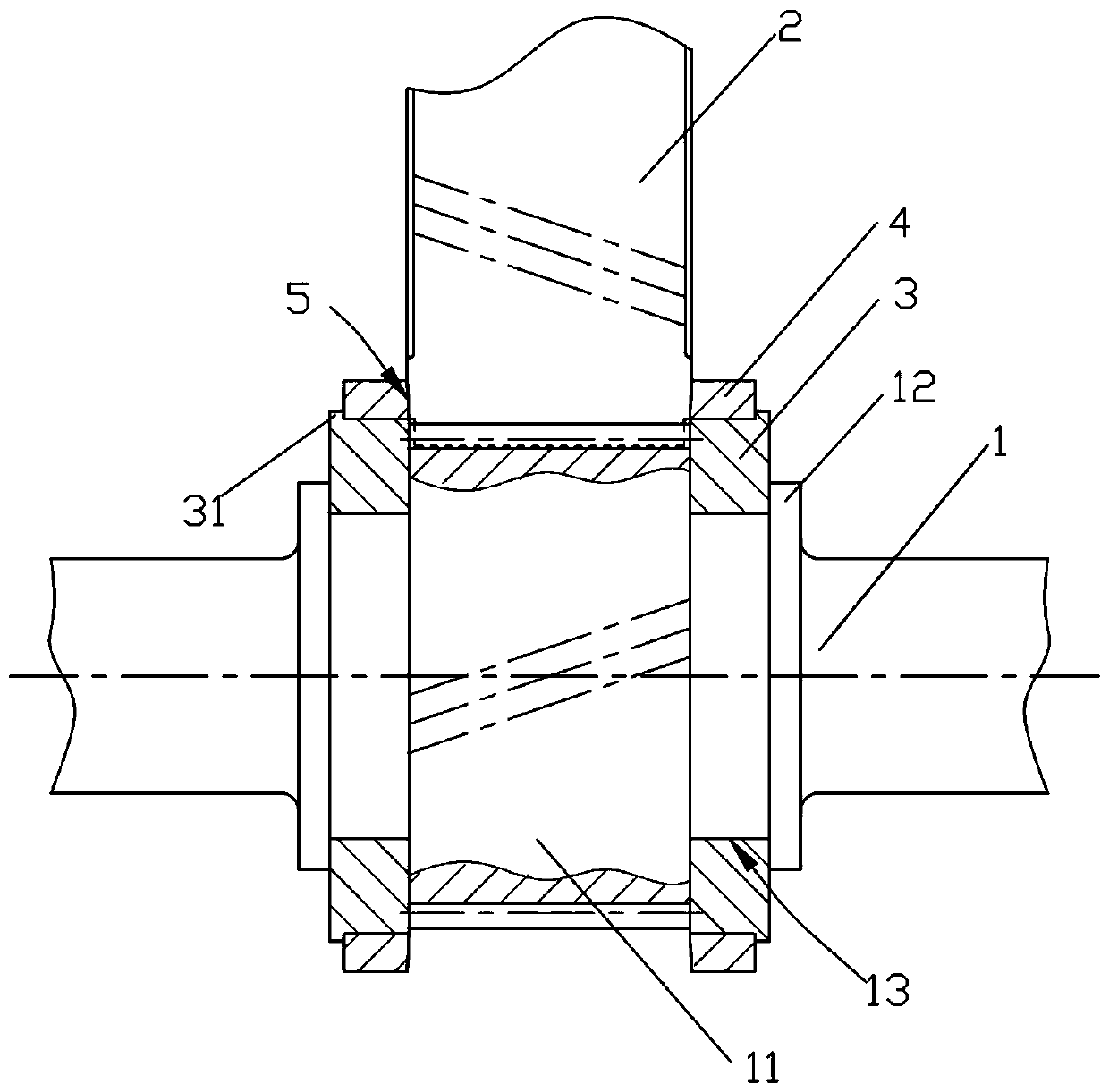
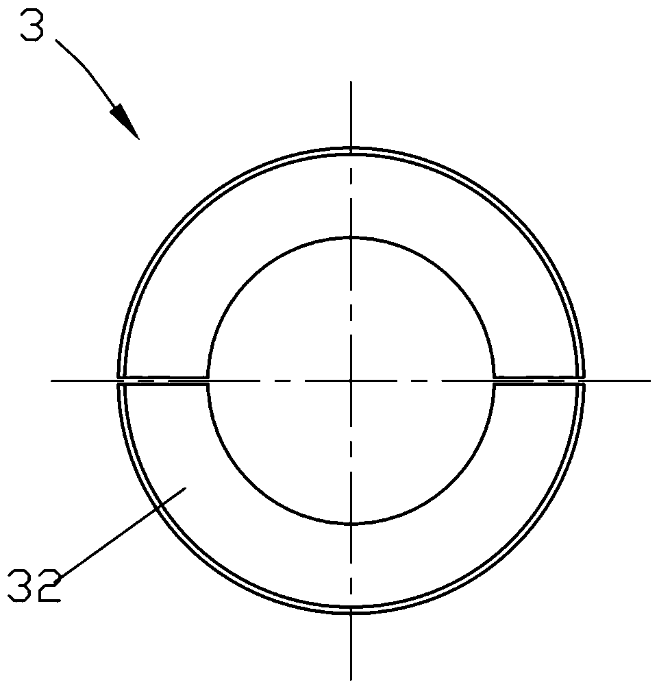
[0030] like Figure 1-Figure 2 As shown, the embodiment of the present invention discloses a thrust plate structure of a high-speed gearbox, including a high-speed gear shaft 1 and a driving gear 2. Shaft shoulder 12, an annular clamping groove 13 is formed between the gear portion 11 and the shaft shoulder 12, and the retaining ring 3 is set inside the annular clamping groove 13, wherein the retaining ring 3 is composed of two semi-circular rings 32, which are Firstly process it into a ring as a whole, and then use wire cutting to separate and form two semi-circular rings 32. Any retaining ring 3 is fitted with a thrust disc 4, and the thrust disc 4 and the retaining ring 3 are an interference fit. The thrust surface 5 is formed by contacting the ...


PUM


Abstract

The invention discloses a high-speed gearbox thrust disc structure. The high-speed gearbox thrust disc structure comprises a high-speed gear shaft and a driving gear. The high-speed gear shaft comprises a gear part engaged with the driving gear, and shaft shoulder parts located on the two sides of the gear part. An annular clamping groove is formed between the gear part and each shaft shoulder part. A check ring is sleeved with each annular clamping groove. Each check ring is sleeved with a thrust disc. The driving gear makes fact contact with one side of each thrust disc so that a thrust facecan be formed. The radial and axial size of the thrust disc structure is small, the structure is compact, and stable rotation of a high-speed shaft is facilitated; and when vibration is measured at the shaft neck position of the high-speed gear and the rotation speed reaches 30,000 r/min, the axial vibration is smaller than or equal to 0.015. According to the thrust disc structure, the componentstructure is simple, the manufacturing cost is low, the gear axial gap can be reliably guaranteed, and playing during work is avoided.

Description

technical field [0001] The invention relates to a mechanical transmission part, in particular to a thrust plate structure of a high-speed gear box with a small axial dimension and a simpler and firmer structure. Background technique [0002] The high-speed gearbox increases the speed through the gear pair with a large transmission ratio, and increases the input speed to a high speed, so that the transmission power is large. For high-speed gearbox gear pairs, in addition to considering the gear strength, the more important thing is the dynamic stability at high speed. In order to improve the coincidence degree of gear transmission and enhance the smooth operation, high-speed gears usually adopt single helical gear transmission. The meshing of single helical gears generates axial force. [0003] In order to bear the axial force on the box body, it is currently the best way to install a thrust plate structure at both ends of the high-speed shaft gear. It is widely used in the...

Claims


Application Information

Patent Timeline
Patent Type & Authority Applications(China)
IPC IPC(8): F16H57/00F16C35/02F16C33/12F16C17/10
CPCF16C17/10F16C33/121F16C35/02F16H57/0018F16C2204/62F16C2204/70F16C2204/74
Inventor 文学良刘波
Owner ZHUZHOU JIUZHOU TRANSMISSION MACHINERY
Why Eureka
Try Eureka