Control device based on flexible triggering of silicon controlled rectifier

A control device, a sensitive technology, applied in flow control, non-electric variable control, control/regulation system, etc., can solve problems such as inability to increase humidity, influence of staff, poor impurity removal effect, etc., to achieve fast reactive power change, The effect of quick switching

Active Publication Date: 2018-03-20
CHONGQING CASEY YI ELECTRONICS TECH CO LTD
View PDF7 Cites 0 Cited by
  • Summary
  • Abstract
  • Description
  • Claims
  • Application Information

AI Technical Summary

Problems solved by technology

And the concentration of its gaseous pollutants must be less than 1ppt in the factory building of making electronic products, therefore, in order to filter and remove dust, the existing method all is to arrange chemical filter at the air inlet of the fan on the ceiling of the factory building to reduce dust, and For the current conventional chemical filter, in the initial state, its effect of adsorbing organic pollutants is better, and clean air with lower pollutant concentration can be obtained, but as the use time is prolonged, its impurity removal effect will become more and more serious. The worse the situation, the higher the concentration of pollutants in the obtained clean air
[0003] On the other hand, the chemical filter can only filter the gas in the factory building alone, but cannot increase the humidity in the factory building. In the factory building, it will affect the staff in the factory building, and it is not necessary to discharge dust in the factory building every day. When it is not discharged, the air inlet of the factory building will not be closed. and sensitive trigger thyristor-based control devices for dust emission control

Method used


Image

  • Control device based on flexible triggering of silicon controlled rectifier
  • Control device based on flexible triggering of silicon controlled rectifier
  • Control device based on flexible triggering of silicon controlled rectifier

Examples


Embodiment Construction

[0020] The present invention will be described in further detail below by means of specific embodiments:

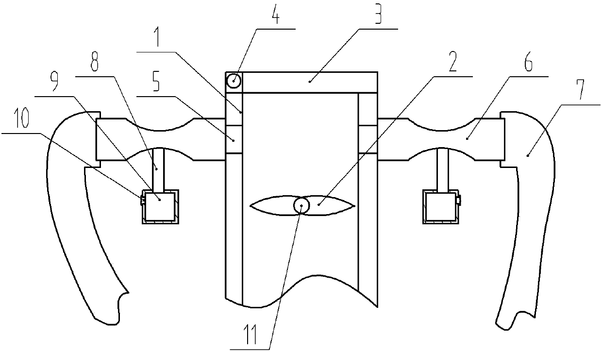
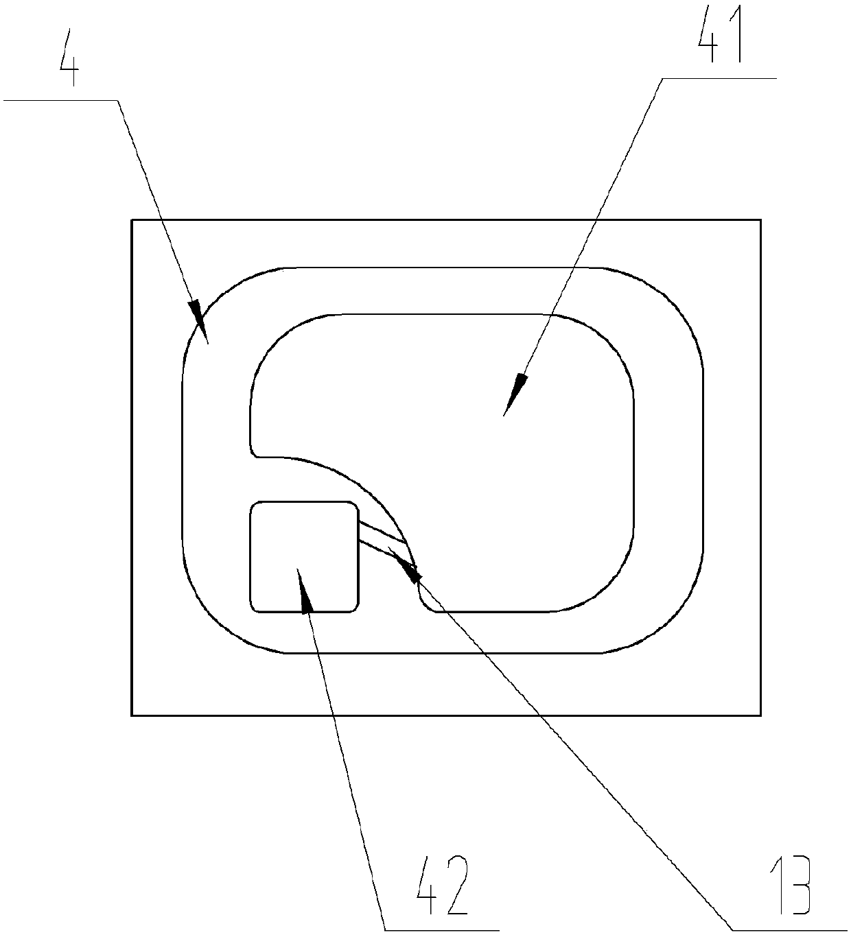
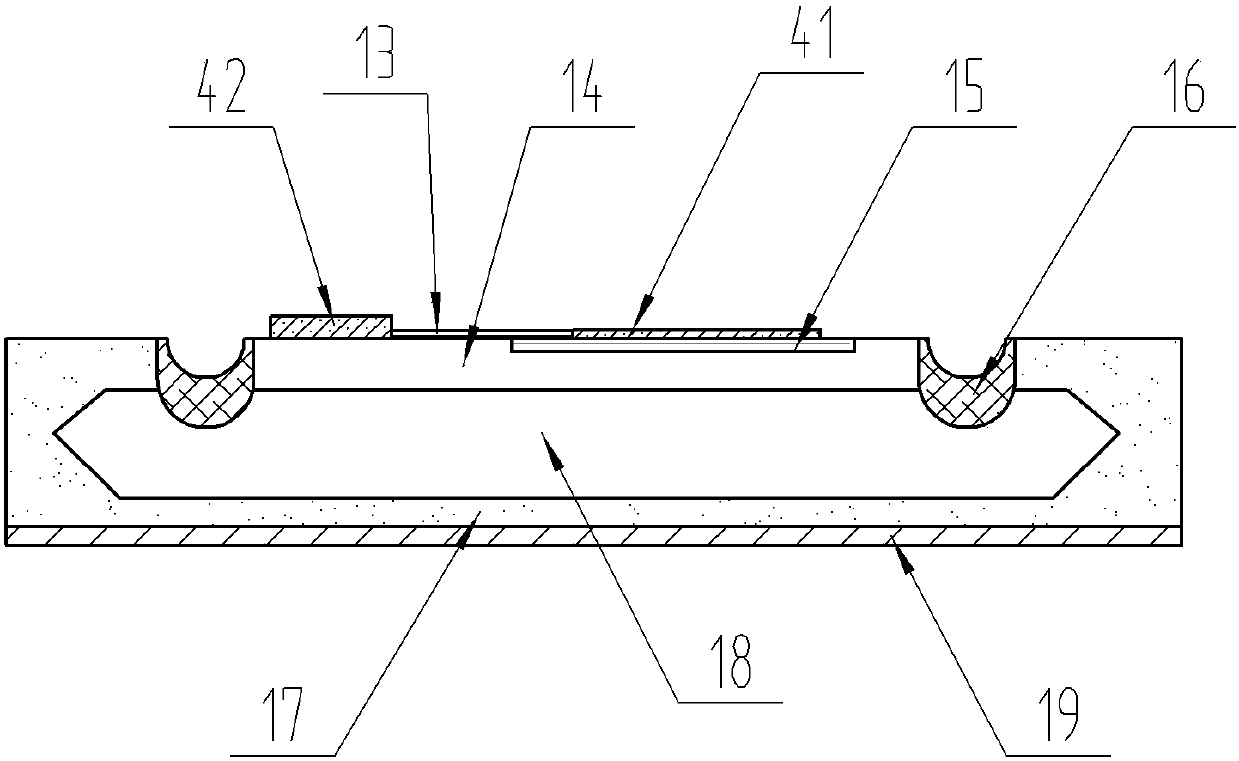
[0021] The reference signs in the drawings of the specification include: flue pipe 1, fan blade 2, solenoid valve 3, thyristor 4, cathode electrode K41, gate electrode G42, through hole 5, Venturi tube 6, hose 7, Water pipe 8, water tank 9, cork 10, rotating shaft 11, resistance 13, P-type short base area 14, N+ type emission area 15, glass passivation 16, P-type anode area 17, N-type long base area 18, anode electrode A19.

[0022] Such as figure 1 As shown, the control device based on the sensitive trigger silicon controlled rectifier in this embodiment includes a flue pipe 1, the flue pipe 1 is provided with a rotating shaft 11, one end of the rotating shaft 11 is fixedly connected to the output shaft of the motor, and the rotating shaft 11 is There is a fan blade 2 fixed on one end. When the motor is started, the motor drives the rotating shaft 11 to rotate, and the...


PUM


Abstract

The invention discloses a control device based on the flexible triggering of a silicon controlled rectifier, and the device comprises a flue pipe and a motor disposed outside the flue pipe. The interior of the flue pipe is provided with a rotating shaft, wherein one end of the rotating shaft is fixed on the motor, and the other end of the rotating shaft is fixedly provided with a fan blade. The blade surface of the fan blade faces the mouth of the flue pipe, and the mouth of the flue pipe is provided with a solenoid valve. The device also comprises a silicon controlled rectifier switch and twoflexible pipes, and the silicon controlled rectifier switch is electrically connected with the solenoid valve. Two sides of the flue pipe are respectively provided with through holes, and the two through holes are located at the upper part of the flue pipe. Two sides of the flue pipe are respectively provided with a Venturi tube, and a throat part of each Venturi tube is provided with a water pipe. A water tank is disposed below the Venturi tubes, and the water tank is connected with the water pipes. One end of each Venturi tube is communicated with one through hole, and the end of each Venturi tube is connected with one flexible pipe. According to the scheme of the invention, water, dust and air are integrated to form water mist through the Venturi tubes, and the water mist is sprayed tothe interior of a workshop, thereby reducing the dust in the workshop, and also increasing the humidity of the workshop.

Description

technical field [0001] The invention belongs to the technical field of thyristors, in particular to a control device based on sensitive trigger thyristors. Background technique [0002] With the development of high and new technologies such as electronics, the concentration of pollutants in the environment may often cause electrical drift or instability to products. And the concentration of its gaseous pollutants must be less than 1ppt in the factory building of making electronic products, therefore, in order to filter and remove dust, the existing method all is to arrange chemical filter at the air inlet of the fan on the ceiling of the factory building to reduce dust, and For the current conventional chemical filter, in the initial state, its effect of adsorbing organic pollutants is better, and clean air with lower pollutant concentration can be obtained, but as the use time is prolonged, its impurity removal effect will become more and more serious. The worse it is, the...

Claims


Application Information

Patent Timeline
Patent Type & Authority Applications(China)
IPC IPC(8): G05D7/06B01D47/06
CPCB01D47/06G05D7/0635
Inventor 魏广乾
Owner CHONGQING CASEY YI ELECTRONICS TECH CO LTD
Why Eureka
Try Eureka