Check patentability & draft patents in minutes with Patsnap Eureka AI!

MVR (Mechanical Vapor Recompression) evaporator and application of MVR evaporator in heat transfer system

An evaporator and secondary steam technology, which is applied in the system field of MVR evaporator heat transfer research, can solve the problems of difficulty in handling concentrated liquid, complex landfill leachate composition, and difficulty in efficient and lasting operation of the MVR evaporation system. Less, simple and flexible operation

Pending Publication Date: 2018-03-23
SOUND ENVIRONMENTAL RESOURCES
View PDF3 Cites 0 Cited by
  • Summary
  • Abstract
  • Description
  • Claims
  • Application Information

AI Technical Summary

Problems solved by technology

[0003] The traditional leachate treatment process is a "biochemical + membrane filtration" treatment process, which will produce high-concentration concentrates that are difficult to handle
The new treatment method of "MVR evaporation + condensate biochemical" for leachate is more environmentally friendly because there is no concentrated liquid, but the composition of landfill leachate is extremely complex, and the composition varies greatly with regions and seasons. Fully understanding the heat transfer characteristics of leachate will be difficult to ensure the efficient and long-lasting operation of the MVR evaporation system. Therefore, it is necessary to study the heat transfer characteristics of leachate during evaporation. It is very important to obtain key parameters in the evaporation process, and then a Applicable Research Method for Heat Transfer Characteristics of MVR Evaporator

Method used


Image

  • MVR (Mechanical Vapor Recompression) evaporator and application of MVR evaporator in heat transfer system

Examples


Embodiment Construction

[0018] The present invention will be further described below in conjunction with the accompanying drawings, but the protection scope of the present invention is not limited thereto.

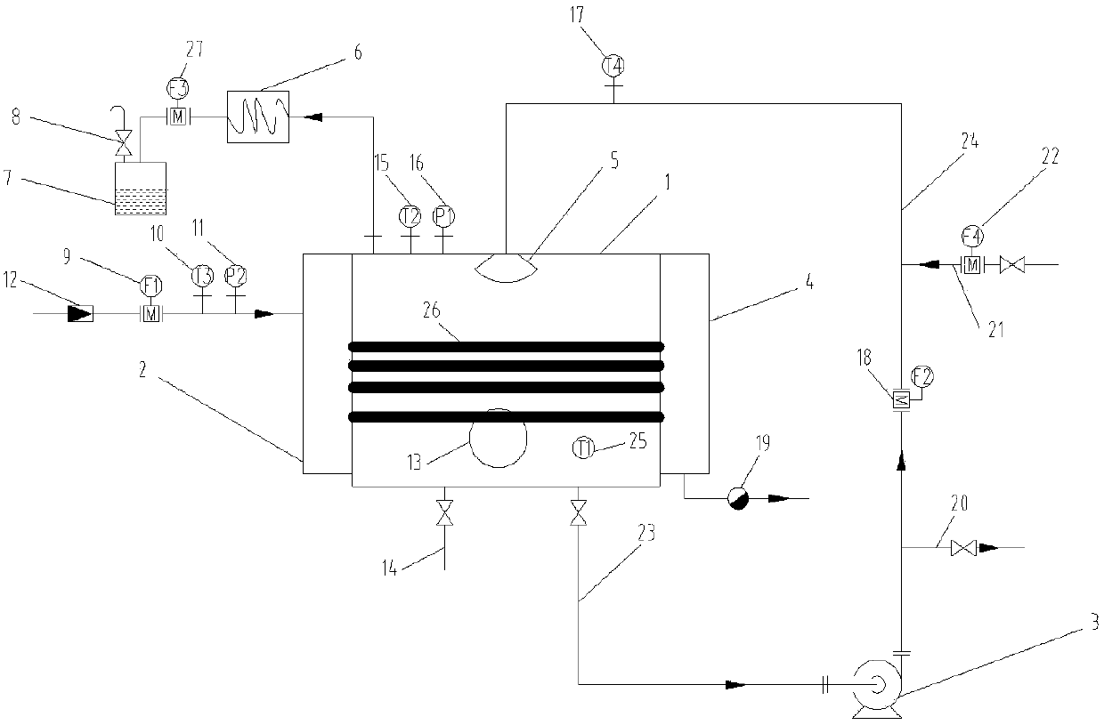
[0019] See attached figure 1 The evaporator body 1 is a cylindrical structure, and the two ends of the cylinder are welded and sealed with two steel plates with round holes. The heat exchange tube 26 is placed in the evaporator through the round holes of the steel plate and sealed with the cylinder through an O-shaped silica gel pad. Heat preservation measures are taken on the outer surface of the cylinder to reduce heat dissipation of the system. The nozzle selected by the liquid distributor 5 ensures that the heat exchange tube 26 distributes the liquid evenly. The steam distributor 2 and the condensed water collector 4 are located at both ends of the cylinder. The pipe 26 is sealed, the frequency conversion circulating pump 3 is located on the ground next to the evaporator, the bottom of the e...


PUM


Abstract

The invention relates to an MVR (Mechanical Vapor Recompression) evaporator and application. A circular pump inlet pipeline, a frequency conversion circulating pump, a leachate inlet and a circulatingpump outlet pipeline are sequentially arranged on a circular inlet / outlet pipeline; a steam throttling valve, a stream flowmeter, a steam thermometer and a steam pressure gauge are respectively arranged on a pipeline body of a steam pipeline; a secondary steam condensate water flow meter is arranged on a pipeline of a secondary steam condenser and a secondary steam condensate water collector; a concentrate thermometer is arranged at the middle part of an evaporator body; a liquid distributor is communicated with a pipeline body of the circular pump outlet pipeline; a secondary steam outlet iscommunicated with a secondary steam condensation pipeline; a drain valve is arranged at the lower part of the condensate water collector; a liquid outlet is communicated with the circular inlet / outlet pipeline. The MVR evaporator disclosed by the invention is provided with the frequency conversion circulating pump and the steam throttling valve, so that steam pressure can be flexibly adjusted andheated, and the flow of circulating liquid also can be adjusted; compared with other evaporation systems, the MVR evaporator has the advantages of few used equipment and simple and flexible operation.

Description

technical field [0001] The invention relates to a system suitable for heat transfer research of an MVR evaporator, which belongs to the technical field of environmental protection equipment. Background technique [0002] The treatment of leachate from urban waste landfills and incineration plants has always been a very difficult problem in the design, operation and management of landfills and incineration plants. The leachate mainly comes from precipitation and the embedded water of the garbage itself. Since many factors may affect the properties of the leachate during the flow of the liquid, including physical factors, chemical factors and biological factors, the properties of the leachate vary within a considerable range. Generally speaking, its pH value is between 4 and 9, COD is in the range of 2000 to 62000mg / L, BOD5 is from 600 to 45000mg / L, ammonia nitrogen content is usually 100 to 1000mg / L, heavy metal concentration and heavy metal in municipal sewage The concentr...

Claims


Application Information

Patent Timeline
IPC IPC(8): B01D1/22B01D1/00
CPCB01D1/0082B01D1/22
Inventor 马跃辉郝永俊李卜涛李顺兴曾国杰张丽新康斌项宇宸
Owner SOUND ENVIRONMENTAL RESOURCES
Features
  • R&D
  • Intellectual Property
  • Life Sciences
  • Materials
  • Tech Scout
  • Unparalleled Data Quality
  • Higher Quality Content
  • 60% Fewer Hallucinations
Learn More