
Filtering-type air drier

An air dryer and filter drying technology, which is applied in the direction of dispersed particle filtration, gas treatment, membrane technology, etc., can solve the problems of short service life, high power consumption, and high energy consumption, so as to improve service life and cleanliness degree, drying effect is good

Inactive Publication Date: 2018-03-23
夏放军
View PDF0 Cites 2 Cited by
  • Summary
  • Abstract
  • Description
  • Claims
  • Application Information

AI Technical Summary

Problems solved by technology

The water city device in the compressed air is the biggest hidden danger to the normal operation of the pneumatic system. In the purification process of the pneumatic system, the drying of the compressed air is the most important, and the cost paid for this is also the highest, and it will also generate noise and dust
[0003] The compressed air dryers commonly used in China now use refrigerated or heated dryers. The refrigerated dryer uses the principle of air-conditioning compressors to refrigerate and condense compressed air to dry compressed air. The drying effect is poor and the power consumption is high. The heating dryer uses electric heating to dry the air, but the energy consumption is very high. Although the use of these two dryers can dehumidify and dry the air, they cannot filter the air while drying, resulting in dryness. The air still has a peculiar smell, which not only puts pressure on the company's electricity and energy consumption costs, but also fails to meet the company's product requirements for compressed air dew point quality
For the president, the existing air dryers have the disadvantages of poor drying effect, high energy consumption and short service life

Method used


Image

  • Filtering-type air drier
  • Filtering-type air drier

Examples


Embodiment 1

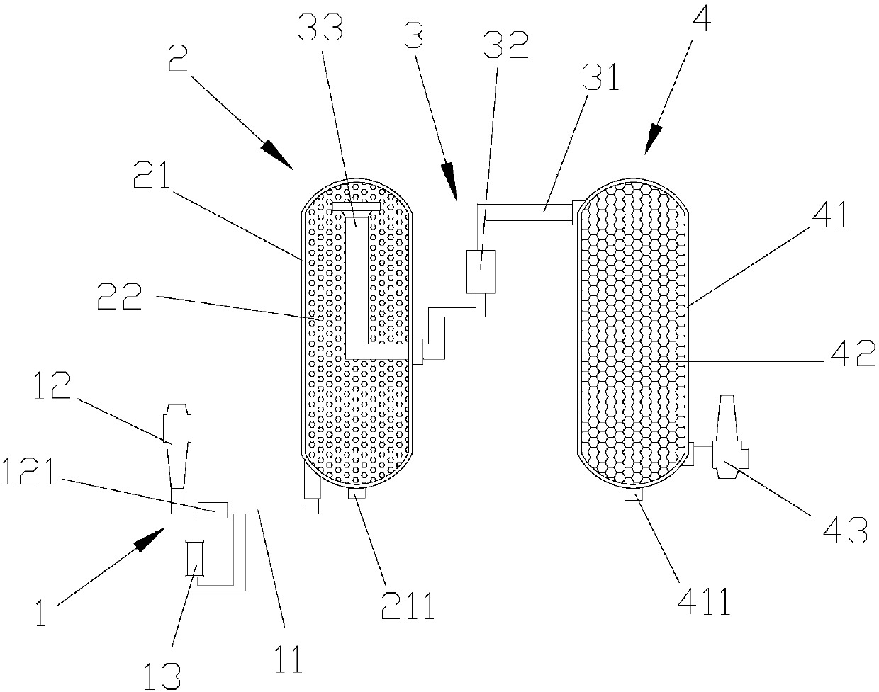
[0029] A filter-type air dryer, such as figure 1 As shown, it includes an air intake device 1, and a first drying tank 2 arranged on one side of the air intake device 1 and communicated with the air intake device 1 for filtering and drying the air, and a first drying tank 2 arranged on the first drying tank 2 on one side and communicated with the first drying tank 2, a communication device 3 for conveying air, and a second drying tank 4 arranged on the side of the communication device 3 for filtering and drying the air; The air intake device 1 includes a pipe body 11, an air inlet 12 arranged at the head end of the pipe body 11 and fixed with the pipe body 11 by welding, and an air inlet 12 arranged in the middle of the pipe body 11 and fixed with the pipe body 11 by screwing. The connected muffler 13 can reduce the noise generated when the air is input, and the lower end of the air inlet 12 is provided with a valve 121 for controlling the air entering. In this embodiment, th...

Embodiment 2

[0042] A filter-type air dryer, such as figure 1 As shown, it includes an air intake device 1, and a first drying tank 2 arranged on one side of the air intake device 1 and communicated with the air intake device 1 for filtering and drying the air, and a first drying tank 2 arranged on the first drying tank 2 on one side and communicated with the first drying tank 2, a communication device 3 for conveying air, and a second drying tank 4 arranged on the side of the communication device 3 for filtering and drying the air; The air intake device 1 includes a pipe body 11, an air inlet 12 arranged at the head end of the pipe body 11 and fixed with the pipe body 11 by welding, and an air inlet 12 arranged in the middle of the pipe body 11 and fixed with the pipe body 11 by screwing. The connected muffler 13 can reduce the noise generated when the air is input, and the lower end of the air inlet 12 is provided with a valve 121 for controlling the air entering. In this embodiment, th...

Embodiment 3

[0055] A filter-type air dryer, such as figure 1 As shown, it includes an air intake device 1, and a first drying tank 2 arranged on one side of the air intake device 1 and communicated with the air intake device 1 for filtering and drying the air, and a first drying tank 2 arranged on the first drying tank 2 on one side and communicated with the first drying tank 2, a communication device 3 for conveying air, and a second drying tank 4 arranged on the side of the communication device 3 for filtering and drying the air; The air intake device 1 includes a pipe body 11, an air inlet 12 arranged at the head end of the pipe body 11 and fixed with the pipe body 11 by welding, and an air inlet 12 arranged in the middle of the pipe body 11 and fixed with the pipe body 11 by screwing. The connected muffler 13 can reduce the noise generated when the air is input, and the lower end of the air inlet 12 is provided with a valve 121 for controlling the air entering. In this embodiment, th...


PUM


Abstract

The invention discloses a filter-type air dryer, which comprises an air inlet device, a first drying tank arranged on one side of the air inlet device and communicated with the air inlet device, and a communication device arranged on one side of the first drying tank , and the second drying tank arranged on one side of the communication device; the first drying tank includes a first tank body, and saturated ceramic balls filled inside the first tank body; the second drying tank includes a second tank body , and the unsaturated ceramic balls filled inside the second tank, and the outlet arranged under one side of the second tank and communicated with the second tank; There are saturated alumina ceramic balls and unsaturated alumina ceramic balls, which can dry the air and filter at the same time, which can improve the cleanliness of the air, and the alumina ceramic balls used to filter dry air have regeneration function, which can Continuous use, so it has the advantages of good drying effect, low energy consumption and long service life.

Description

technical field [0001] The invention relates to a filter type air dryer. Background technique [0002] Today, with the increasing economic development, almost every industrial production plant needs compressed air, and compressed air has become an indispensable power source. With the needs of the development of science and technology, industrial production and industrial products have higher requirements on the quality of air sources, so various air purification equipment have emerged as the times require. The water city device in the compressed air is the biggest hidden danger to the normal operation of the pneumatic system. In the purification process of the pneumatic system, the drying of the compressed air is the most important, and the cost paid for this is also the highest, and it will also generate noise and dust. [0003] The compressed air dryers commonly used in China now use refrigerated or heated dryers. The refrigerated dryer uses the principle of air-condition...

Claims


Application Information

Patent Timeline
IPC IPC(8): B01D53/28B01D46/00B01D46/30B01D53/04B01D53/26C04B35/10C04B35/622C04B35/64
CPCB01D53/28B01D46/0036B01D46/30B01D53/0407B01D53/261B01D2253/104B01D2253/106B01D2253/112B01D2258/06C04B35/10C04B35/622C04B35/64C04B2235/3208C04B2235/3225C04B2235/3418C04B2235/3445C04B2235/3472C04B2235/349C04B2235/3873C04B2235/422C04B2235/602C04B2235/6567
Inventor 夏放军
Owner 夏放军
Learn More