
Thermal power boiler denitrification system flow field optimization device

A technology for optimizing devices and boilers. It is applied in chemical statistics, chemical machine learning, chemical data mining, etc., and can solve problems such as unreasonable distribution of SCR denitration flue gas flow field.

Pending Publication Date: 2018-03-23
SHANXI UNIV
View PDF0 Cites 8 Cited by
  • Summary
  • Abstract
  • Description
  • Claims
  • Application Information

AI Technical Summary

Problems solved by technology

[0005] The purpose of the present invention is to solve the problem of unreasonable distribution of flue gas flow field in SCR denitrification of large-scale thermal power boilers, especially in the case of different degrees of catalyst deactivation. ping "Catalyst Expected Remaining Lifetime"

Method used


Image

  • Thermal power boiler denitrification system flow field optimization device
  • Thermal power boiler denitrification system flow field optimization device
  • Thermal power boiler denitrification system flow field optimization device

Examples


Embodiment Construction

[0022] The principles and features of the present invention are described below in conjunction with the accompanying drawings, and the examples given are only used to explain the present invention, and are not intended to limit the scope of the present invention.

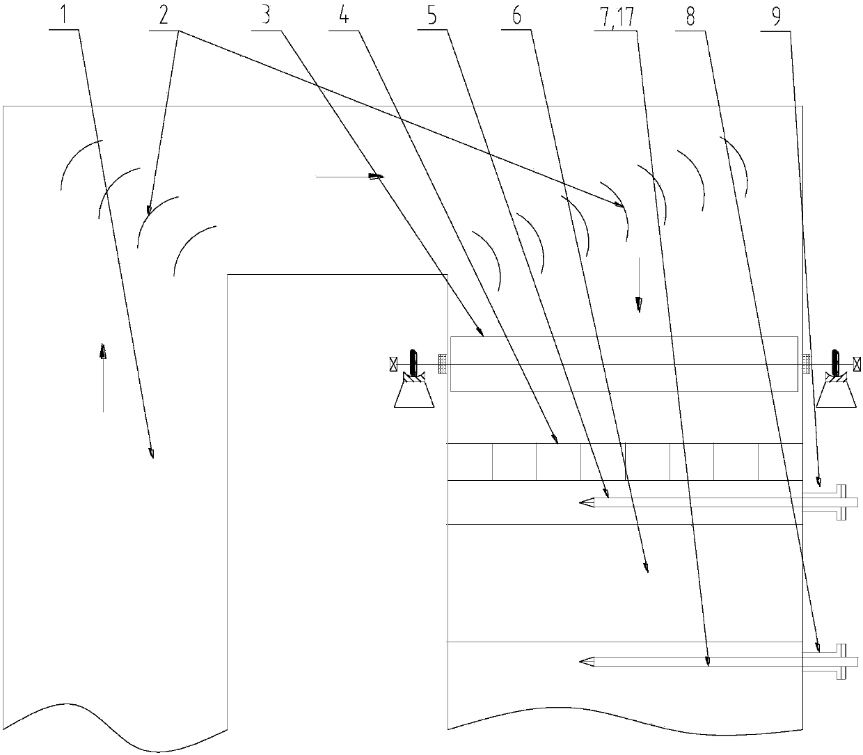
[0023] like figure 1 As shown, the denitrification system of the thermal power boiler in this embodiment includes a fixed deflector 2, a rectifying grid 4 and a catalyst layer 6, and the fixed deflector 2 is installed on the rising section of the denitrification flue 1 of the thermal power boiler (according to the flue gas flow direction , the same below) and the connection between the horizontal section and the connection between the horizontal section and the descending section, the rectifying grid 4 and the catalyst layer 6 are installed in the descending section of the denitrification flue 1 of the thermal power boiler from top to bottom;

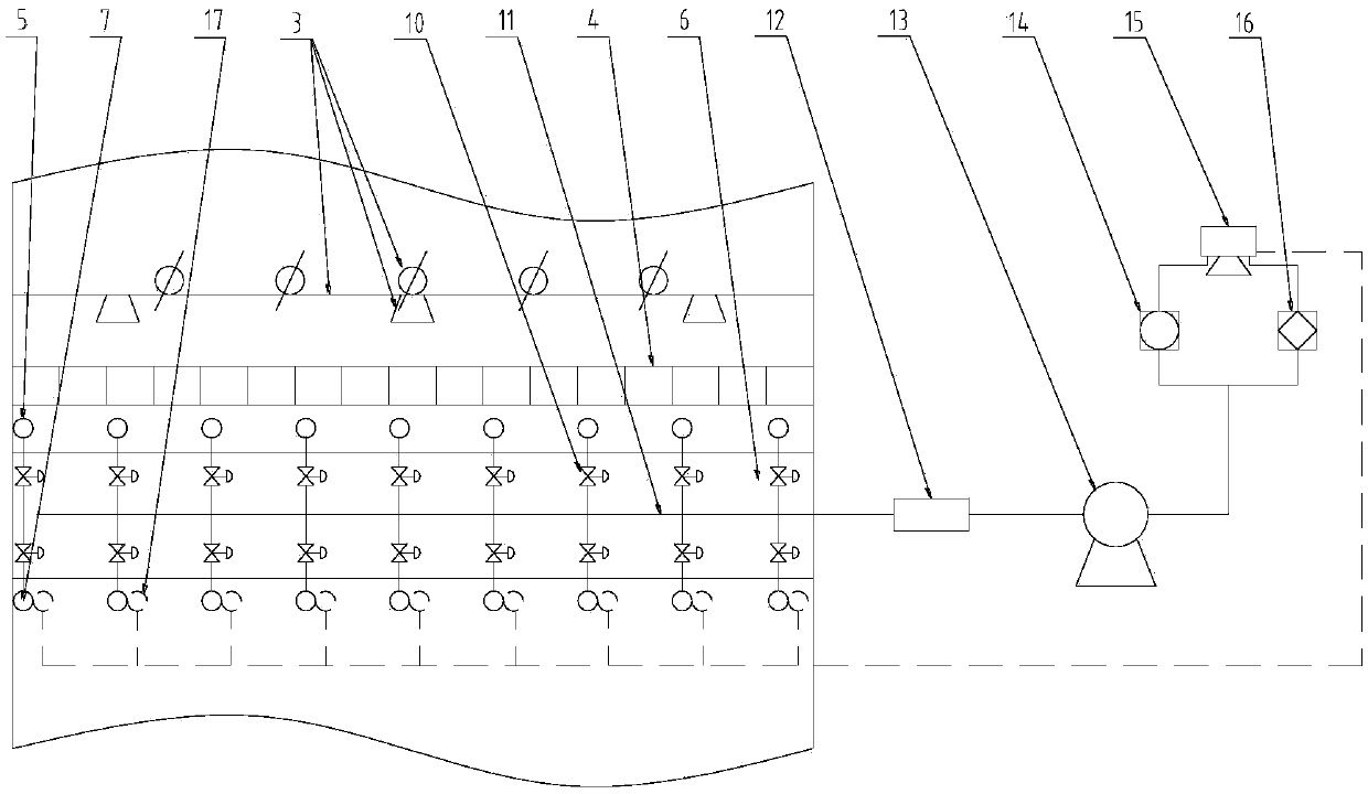
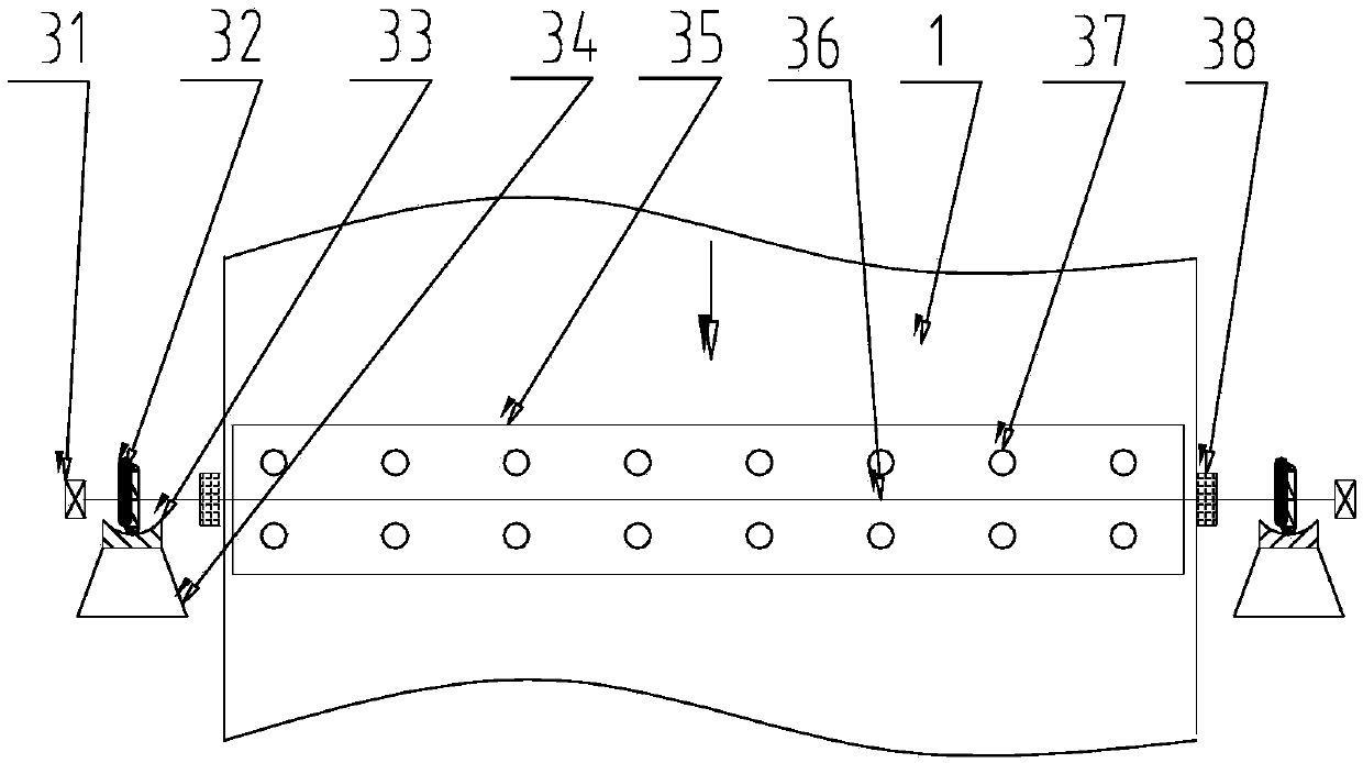
[0024] like Figure 1-3As shown, a flow field optimization device for a...


PUM


Abstract

The invention relates to a thermal power boiler denitrification system flow field optimization device, aiming to solve the problem of unreasonable distribution of a thermal power boiler SCR denitrification smoke flow field. The device mainly comprises a movable porous air distributor assembly, a high-temperature-resistant online flow rate measuring instrument, catalyst layer inlet and outlet sampling guns, catalyst layer inlet and outlet test holes, a sampling tube electric switch, a sampling header, a sampling pump, a smoke analyzer, an online ammonia concentration analyzer, a computer processing system and the like. According to data such as smoke flow rate, concentration of nitrogen oxides and escape ammonia concentration, the device can be used for calculating activity index of catalysts in different area on line, and automatically computing smoke flow rate dynamic allocation schemes, and further can realize online adjustment of the smoke flow field by the movable porous air distributor assembly, so that ammonia escape is reduced to the utmost extent, residual service lives of the catalysts can be balanced, and maintenance cost of the boiler catalysts can be lowered.

Description

technical field [0001] The invention belongs to the field of SCR denitrification of large thermal power boilers, and in particular relates to a flow field optimization device of a thermal power boiler denitrification system. Background technique [0002] There are many problems in the actual operation of the SCR denitrification system of thermal power coal-fired boilers in my country: catalyst clogging and wear, air preheater corrosion and clogging, short catalyst life, and different degrees of catalyst deactivation. To a certain extent, these problems are closely related to the distribution of the flue field of the denitrification system: in the area of ​​high flue gas flow rate, the catalyst workload is large, which makes the catalyst wear and poisoning aging more serious, resulting in a decrease in catalyst activity, and ammonia escape in this area The increase will eventually lead to corrosion and ash blocking of the air preheater; on the contrary, in the area with low f...

Claims


Application Information

Patent Timeline
IPC IPC(8): B01D53/86B01D53/56G06F19/00G06Q10/04G06Q50/06
CPCB01D53/8625G06Q10/04G06Q50/06G16C20/70G16C20/80B01D2258/0283
Inventor 闫高程
Owner SHANXI UNIV
Learn More