
High-efficient sewage stirring device

A stirring device, high-efficiency technology, applied to mixers with rotating stirring devices, mixer accessories, transportation and packaging, etc., can solve the problems of incompatible environmental protection spirit, waste of energy consumption and high purchase cost, and achieve easy promotion, Good mixing effect and convenient operation

Inactive Publication Date: 2018-03-23
合肥挺泰环保科技有限公司
View PDF4 Cites 12 Cited by
  • Summary
  • Abstract
  • Description
  • Claims
  • Application Information

AI Technical Summary

Problems solved by technology

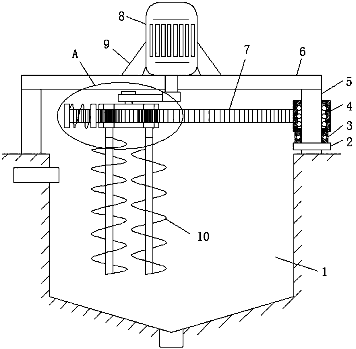
Among them, the stirring link of sewage is indispensable in the link of sewage treatment. The agitator of the existing device rotates independently in the form of stirring. In order to ensure the stirring effect of the whole sewage pool, many agitators are arranged in the sewage pool. Obviously There are defects of high energy consumption and high purchase cost. Of course, in order to solve this problem, some manufacturers have designed and manufactured a stirring device that allows the agitator to switch positions while stirring in the sewage tank. However, in order to achieve the effect of position switching, this Such devices are equipped with another motor or power output source, which is too complicated in structure, and there is a defect of energy waste in terms of energy consumption, which is not in line with the current environmental protection spirit

Method used


Image

  • High-efficient sewage stirring device
  • High-efficient sewage stirring device
  • High-efficient sewage stirring device

Examples


Embodiment Construction

[0017] The following will clearly and completely describe the technical solutions in the embodiments of the present invention with reference to the accompanying drawings in the embodiments of the present invention. Obviously, the described embodiments are only some, not all, embodiments of the present invention.

[0018] In describing the present invention, it should be understood that the terms "upper", "lower", "front", "rear", "left", "right", "top", "bottom", "inner", " The orientation or positional relationship indicated by "outside", etc. is based on the orientation or positional relationship shown in the drawings, and is only for the convenience of describing the present invention and simplifying the description, rather than indicating or implying that the referred device or element must have a specific orientation, so as to Specific orientation configurations and operations, therefore, are not to be construed as limitations on the invention.

[0019] refer to Figure ...


PUM


Abstract

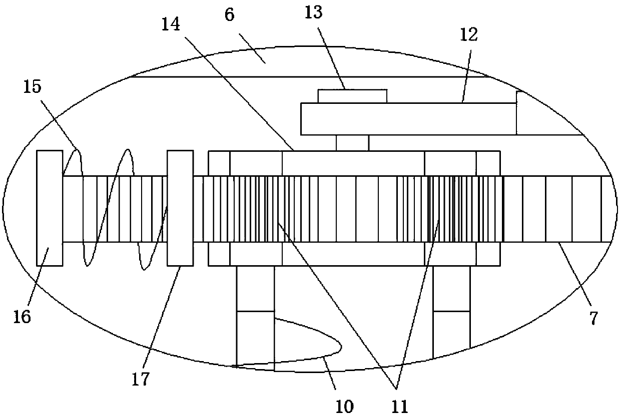
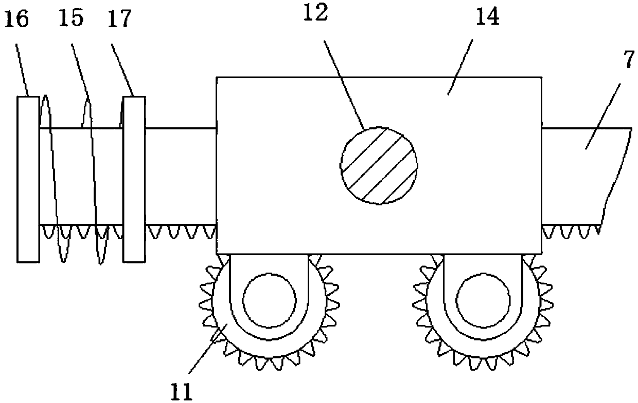
The invention discloses a high-efficient sewage stirring device, which comprises a sewage pond; an end opening part of the sewage pond is fixedly connected with paired upright posts, and one end of each of the paired upright posts far from the sewage pond is fixedly connected with a cross plate; one side of the cross plate far from the upright post is provided with a motor, and the motor is fixedly connected with the cross plate through a motor frame; an output shaft of the motor crosses through the cross plate and extends to the sewage pond, one end of the motor output shaft extended to the sewage pond axially is fixedly sleeved with a crank; one end of the crank far from the motor is hinged with a lug, one end of the lug far from the crank is fixedly connected with a slide block; a rackis glidingly connected to the slide block. By means of a swaying guide rod mechanism, the revolution of the stirrer in the sewage pond is realized; the rack meshed with the gear is arranged on the guide rod, thus the stirrer acquires power from the rack, the revolution and autogiration of the stirrer are realized; the high-efficient sewage stirring device is simple in structure, good in stirring effect, high in efficiency and easy to popularize.

Description

technical field [0001] The invention relates to the field of sewage treatment equipment, in particular to a high-efficiency sewage stirring device. Background technique [0002] With the continuous improvement of my country's urbanization level, the construction of sewage treatment facilities has developed rapidly. The use of existing sewage treatment equipment plays a very important role in sewage treatment. In order to achieve the national emission reduction goals and improve the water environment, we have made great efforts Huge contribution, but the form of sewage treatment is still very severe. Among them, the stirring link of sewage is indispensable in the link of sewage treatment. The agitator of the existing device rotates independently in the form of stirring. In order to ensure the stirring effect of the whole sewage pool, many agitators are arranged in the sewage pool. Obviously There are defects of high energy consumption and high purchase cost. Of course, in ord...

Claims


Application Information

Patent Timeline
Patent Type & Authority Applications(China)
IPC IPC(8): B01F7/30B01F7/24B01F15/00
CPCB01F27/114B01F27/213B01F27/2312B01F27/2322B01F27/805B01F27/85B01F27/922B01F27/953B01F2035/352B01F35/00B01F2101/305
Inventor 吴小飞
Owner 合肥挺泰环保科技有限公司
Learn More