Auxiliary brake mechanism of gearbox

A technology for auxiliary braking and gearbox, which is applied in the direction of braking components, brakes, mechanical brake transmission devices, etc., can solve the problem of affecting the operator's handling experience of gearbox service life, wear of the joint surface of gears and meshing sleeves, and inability to install and replace Problems such as the gear synchronizer can be eliminated to achieve the effect of eliminating the phenomenon of gear hitting, smooth gear shifting, and improving operating comfort

Inactive Publication Date: 2018-03-23
YTO LUOYANG CONSTR MASCH CO LTD
View PDF6 Cites 6 Cited by
  • Summary
  • Abstract
  • Description
  • Claims
  • Application Information

AI Technical Summary

Problems solved by technology

[0002] As a kind of equipment for compacting road surface and road base, road roller is widely used in various construction occasions. In actual construction work, road roller needs to move forward and backward repeatedly during compaction. When it needs to change direction or shift gear, it must be quickly Realization, the single-drum vibratory roller is mainly used as a kind of equipment for compacting road surfaces and road bases. In actual construction, the roller needs to repeatedly move forward and backward during the construction work, and the labor intensity of the operator is relatively high. At the same time, the special gearbox for the roller Because the moment of inertia of the gear is too large, the shift synchronizer cannot be installed, and the shift time is long, which causes poor compaction effect during the vibration compaction and reversing process
During the shifting process, due to the high relative speed between the gears, if the operation is improper during the shifting process, the joint surface between the gear and the meshing sleeve will be severely worn, and even the gear will be hit by the operator's improper operation, which seriously affects the The operator's handling experience and the service life of the gearbox

Method used


Image

  • Auxiliary brake mechanism of gearbox
  • Auxiliary brake mechanism of gearbox
  • Auxiliary brake mechanism of gearbox

Examples


Embodiment Construction

[0020] The technical solutions in the embodiments of the present invention will be clearly and completely described below in conjunction with the accompanying drawings in the embodiments of the present invention. Obviously, the described embodiments are only a part of the embodiments of the present invention, rather than all the embodiments. Based on the embodiments of the present invention, all other embodiments obtained by those of ordinary skill in the art without creative work shall fall within the protection scope of the present invention.

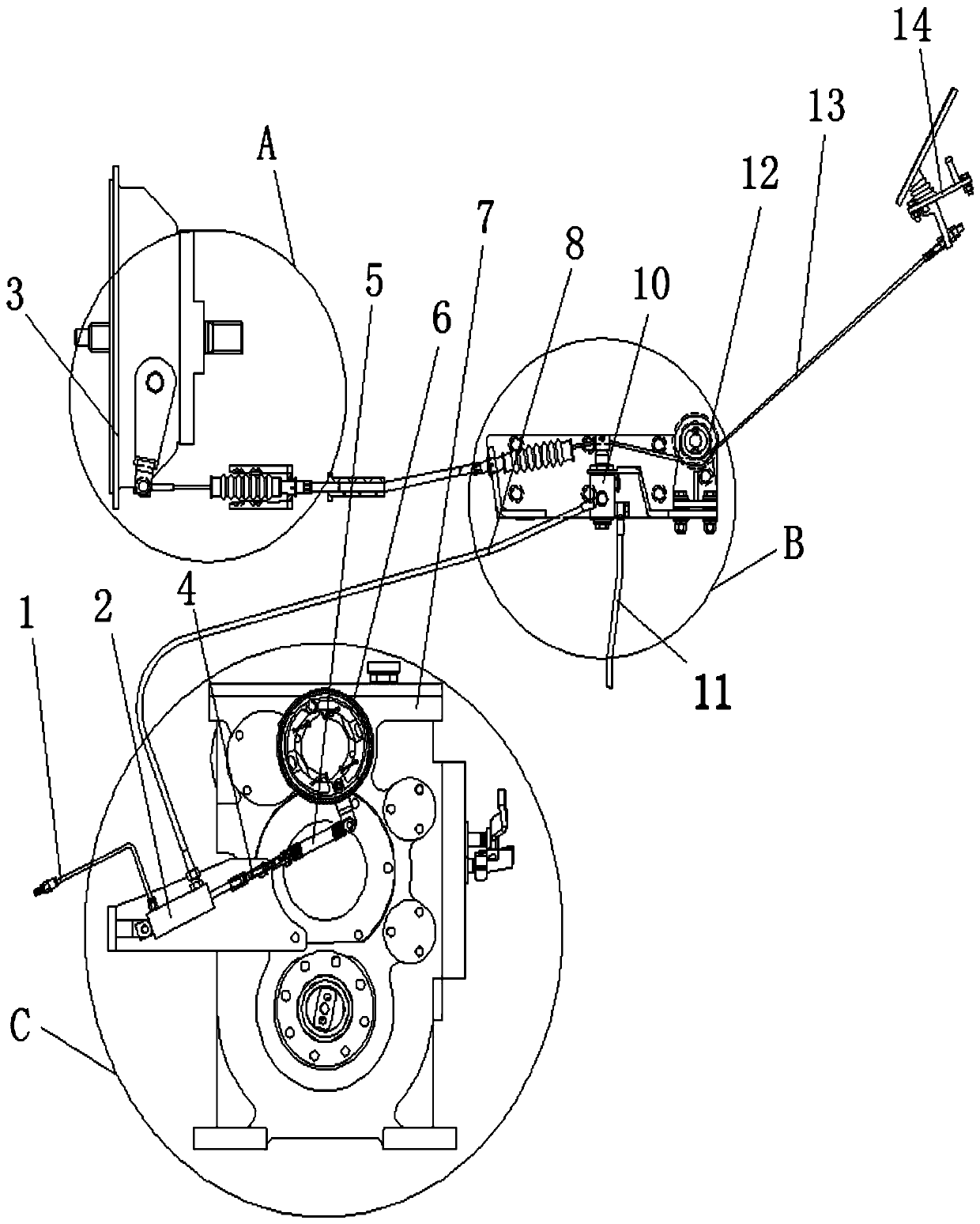
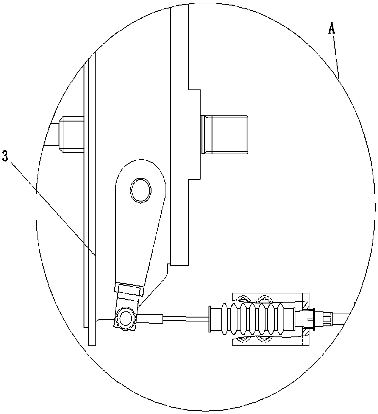
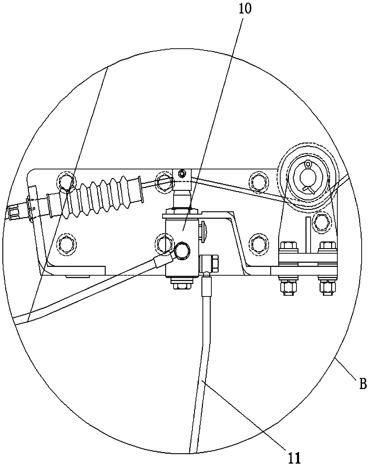
[0021] See Figure 1-4 , The present invention provides a technical solution:

[0022] A gearbox auxiliary braking mechanism, including a clutch pedal, a muffler assembly device with an exhaust pipe 1, a single-acting cylinder 2, a clutch 3 and a drum brake, a muffler assembly device with an exhaust pipe 1 and a single The side of the acting cylinder 2 is connected through, the other side of the single acting cylinder 2 is connected throu...


PUM


Abstract

The invention discloses an auxiliary brake mechanism of a gearbox. The auxiliary brake mechanism comprises a clutch pedal, a muffler combined device with an exhaust pipe, a single-acting cylinder, a clutch and a drum brake, wherein the muffler combined device with the exhaust pipe is connected with the side edge of the single-acting cylinder in a penetrating manner, and the other side edge of thesingle-acting cylinder is connected with one end of a first hose in a penetrating manner; the other end of the first hose is connected with a button valve in a penetrating manner; one end of a secondhose is connected to the lower end of the button valve in a penetrating manner; the button valve is opened and closed through the pulling of one end of a first flexible shaft, and the other end of thefirst flexible shaft goes around guiding wheels of a pulley block and is connected to the clutch pedal; and the control comfortableness of a manipulator is improved, and the gear shifting is smoother. The auxiliary brake mechanism disclosed by the invention is applied to a mechanically-driven single-steel-wheel vibrating roller, so that time for gear shifting is shortened, the labor intensity ofthe manipulator is reduced, the gear shifting is smoother, the manipulation comfortableness of road rolling is improved, and besides, the reliability of a gearbox is improved.

Description

Technical field [0001] The present invention relates to the technical field related to the gearbox of a roller, in particular to a gearbox auxiliary braking mechanism. Background technique [0002] As a kind of compaction equipment for pavement and subgrade layer, road rollers are widely used in various construction occasions. In actual construction work, the rollers need to repeatedly move forward and backward during the work, and they must be fast when changing directions or gears. Realize, the single-drum vibratory roller is mainly used as a compaction equipment for pavement and subgrade. In actual construction, the roller needs to repeatedly move forward and backward during the work time. The operator's labor intensity is relatively large, and the special gearbox for the roller Because the gear moment of inertia is too large, the shift synchronizer cannot be installed, and the shift time is long, which results in poor compaction effect during the vibration compaction reversin...

Claims


Application Information

Patent Timeline
Patent Type & Authority Applications(China)
IPC IPC(8): B60K23/02B60T11/04B60T1/06
CPCB60K23/02B60T1/062B60T11/04
Inventor 韩长太杨建权张学辉董长雷袁飞候艳刚
Owner YTO LUOYANG CONSTR MASCH CO LTD
Why Eureka
Try Eureka