
Inspection method of gas supply system, calibration method of secondary reference device
A calibration method and technology of a reference device, which is applied in the direction of volume measurement instrument/method, volume measurement test/calibration, general control system, etc., can solve the problems of low calculation accuracy, inability to check the change of piping internal volume, and low reliability of gas flow And other issues
- Summary
- Abstract
- Description
- Claims
- Application Information
AI Technical Summary
Problems solved by technology
Method used
Image

Examples
Embodiment Construction
[0044] Hereinafter, various embodiments will be described in detail with reference to the drawings. In addition, in each drawing, the same code|symbol is attached|subjected to the same or corresponding part.
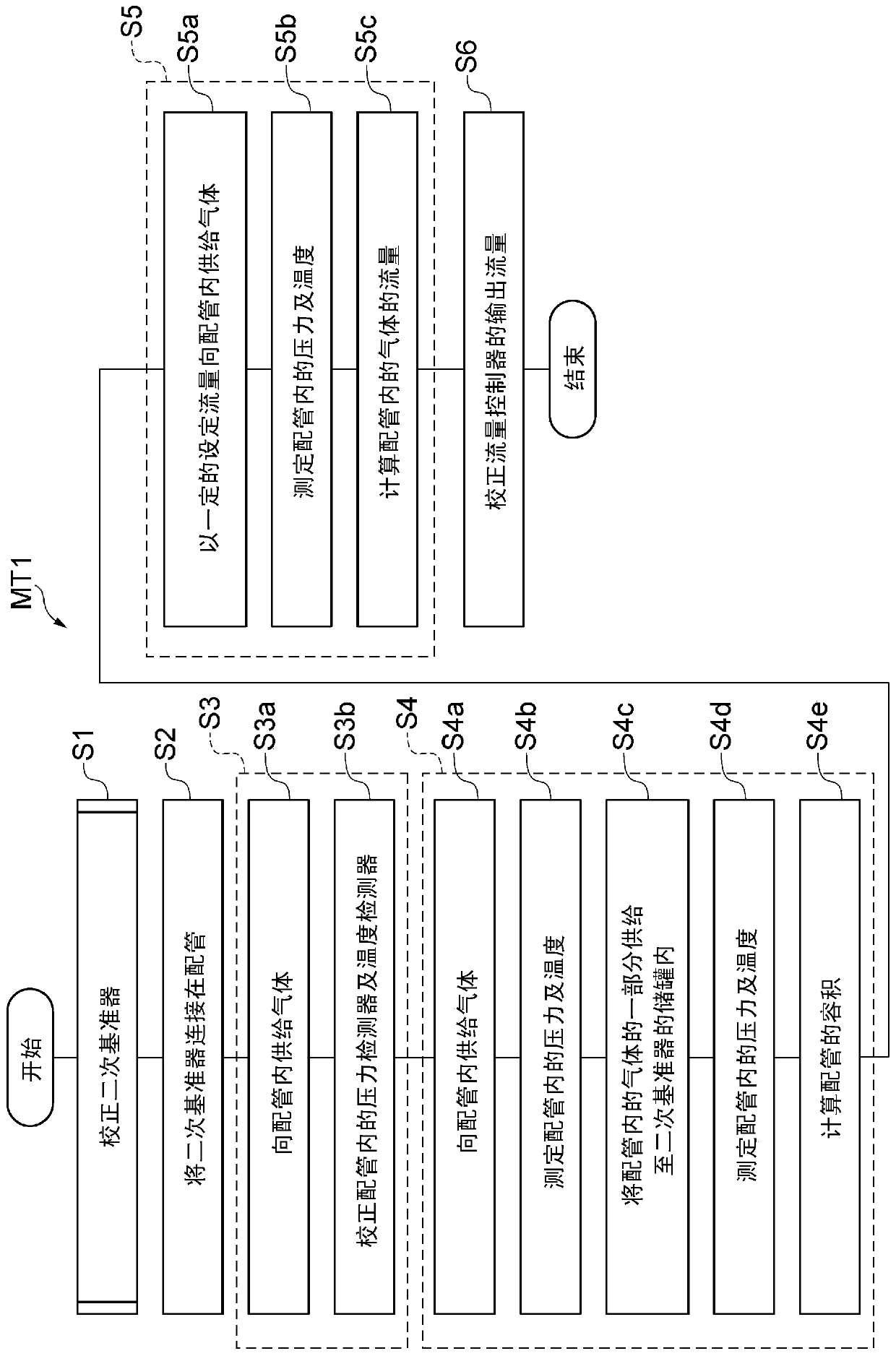
[0045] figure 1 It is a flowchart showing the inspection method of the gas supply system of one embodiment. figure 1 The method MT1 shown is for example applicable to figure 2 The gas supply system 10 is shown.
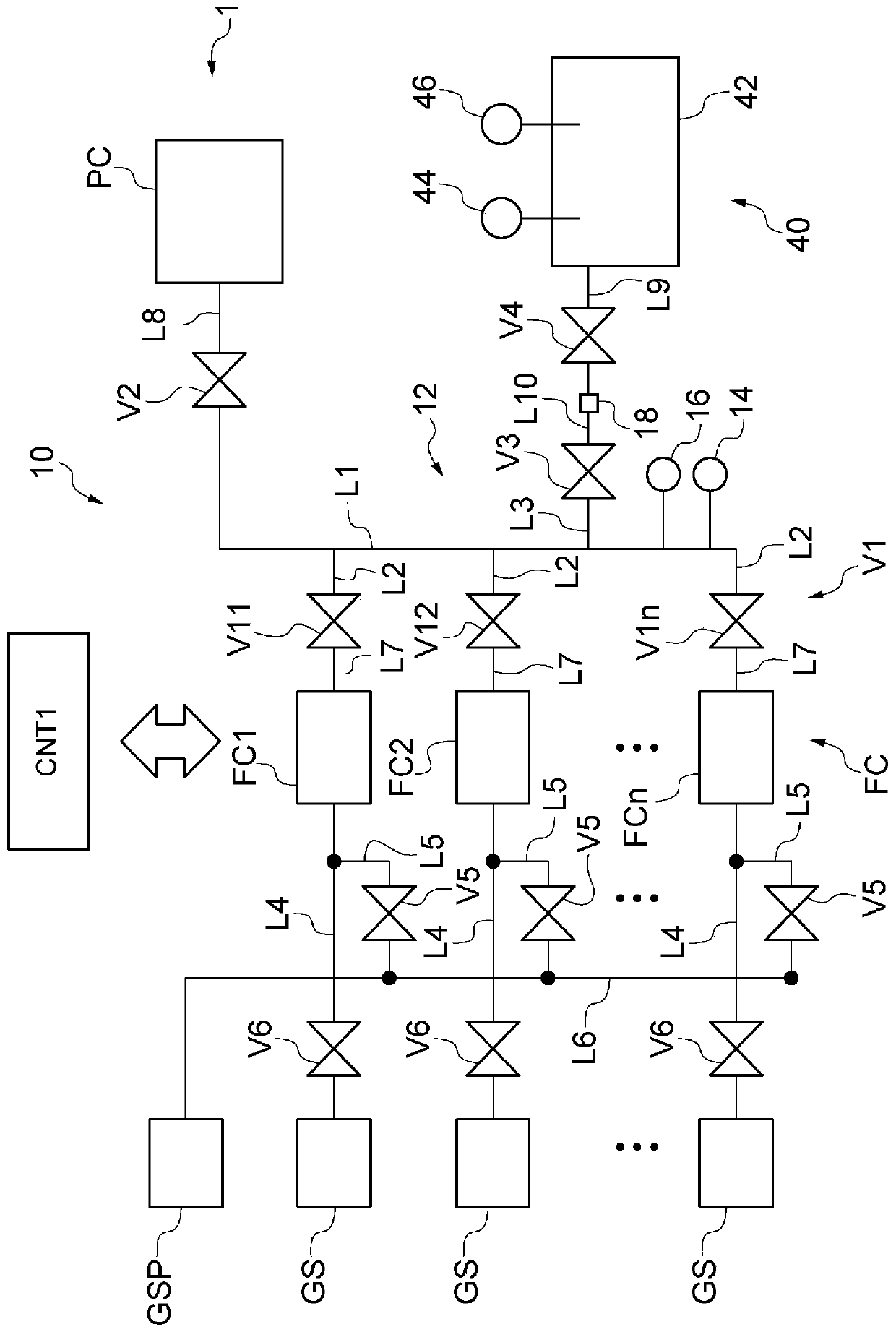
[0046] like figure 2 As shown, the gas supply system 10 has n (n is a positive integer) flow controllers FC1, FC2, ..., FCn, piping 12, n valves (a plurality of first valves of the gas supply system) V11, V12, ..., V1n, valve (second valve of the gas supply system) V2, and valve (third valve of the gas supply system) V3. Hereinafter, when no special distinction is required, the n flow controllers FC1, FC2, ..., FCn are referred to as multiple flow controllers FC, and the n valves V11, V12, ..., V1n are referred to as multiple valves V1.
[0047] Each of...
PUM
 Abstract
Description
Claims
Application Information