Eureka AIR delivers breakthrough ideas for toughest innovation challenges, trusted by R&D personnel around the world.

Drainage channel for water conservancy and hydropower construction

A technology of water conservancy, hydropower and drainage channels, which is applied in water conservancy projects, applications, artificial waterways, etc., can solve problems such as inability to excavate the project, high drainage costs, and affect the progress of the project, and achieve humanized design, long service life, and guaranteed utilization. Effect

Inactive Publication Date: 2018-03-30
成都优速大荣科技有限公司
View PDF0 Cites 1 Cited by
  • Summary
  • Abstract
  • Description
  • Claims
  • Application Information

AI Technical Summary

Problems solved by technology

Abnormal climate change and human factors are the two main causes of thermal pollution in a broad sense, while thermal pollution of water bodies is basically caused by human factors. In the construction of inclined wells, there are often two problems that directly affect the progress of the project. One is the geology of the surrounding rock Stability, the second is the underground aquifer, when the excavation work approaches or penetrates the underground aquifer, there will often be water splashing and water gushing, which will make the excavation of the project impossible, and sometimes the well will be flooded, resulting in production safety accidents. Effective drainage of water in inclined shafts is an important issue in coal mining or tunnel excavation
The existing drainage method for inclined well construction adopts sectioned water bins for pumping and drainage, and water canals are set between the water bins for water diversion. The construction of water pump and drainage system is complicated, and the cost of drainage is high, which affects the construction progress of the inclined well

Method used


Image

  • Drainage channel for water conservancy and hydropower construction
  • Drainage channel for water conservancy and hydropower construction
  • Drainage channel for water conservancy and hydropower construction

Examples


Embodiment Construction

[0017] The following will clearly and completely describe the technical solutions in the embodiments of the present invention with reference to the accompanying drawings in the embodiments of the present invention. Obviously, the described embodiments are only some of the embodiments of the present invention, but not all of them. Based on the embodiments of the present invention, all other embodiments obtained by persons of ordinary skill in the art without making creative efforts belong to the protection scope of the present invention.

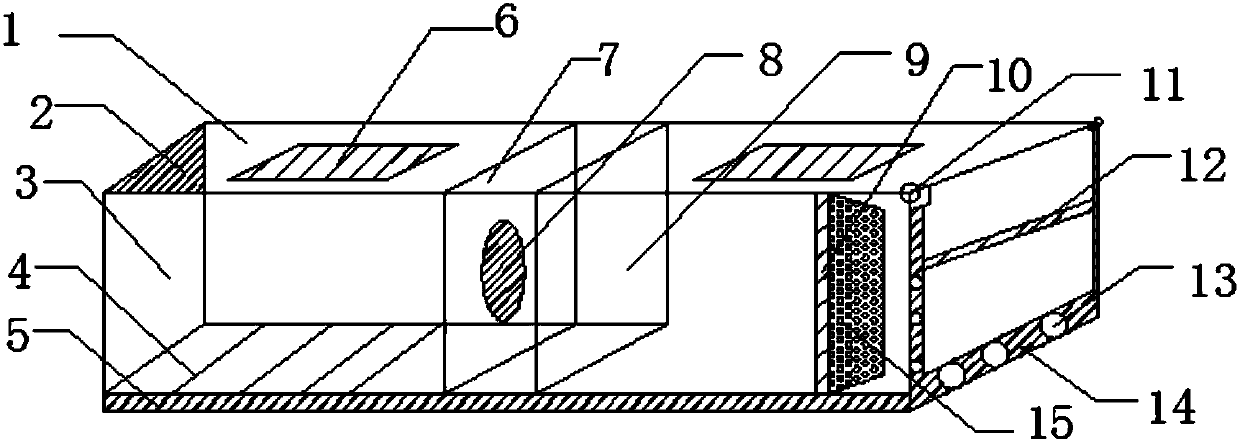
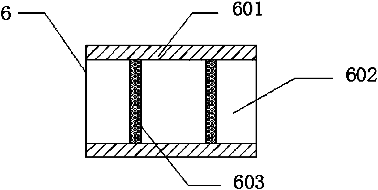
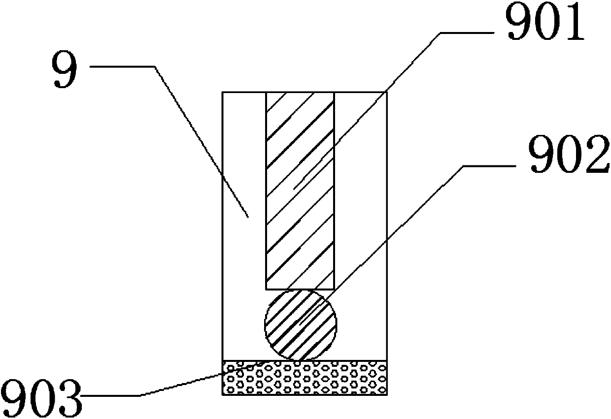
[0018] The present invention provides such figure 1 , figure 2 and image 3 The shown drainage channel for water conservancy and hydropower construction includes a main body 1, the lower left side of the main body 1 is provided with an inlet 2, and the lower right side of the inlet 2 is connected with a coagulation side 3, the A fault rod 4 is fixed on the left side of the lower part of the coagulation side 3, a slide plate 5 is arranged o...


PUM


Abstract

The invention discloses a drainage ditch for water conservancy and hydropower construction, which comprises a main body, the lower left side of the main body is provided with a ditch inlet, the lower right side of the ditch inlet is connected with a coagulation side, and the coagulation side A fault rod is fixed on the left side of the lower part, slide plates are arranged on the left and right sides of the lower part of the fault rod, an air adsorption plate is fixed on the upper right side of the slide plate, and a filter plate is connected to the lower right side of the air adsorption plate. The left side of the lower part of the filter plate is fixed with a filter screen, the upper left side of the filter screen is provided with a flow meter, the lower right side of the flow meter is fixed with a door post, and the upper right side of the door post is connected with a roller, so The lower right side of the roller is fixed with a layering bar, the lower right side of the layering bar is provided with a ball, the lower left side of the ball is provided with a front plate, and the upper left side of the front plate is connected with an automatic door. The drainage channel for water conservancy and hydropower construction is simple in structure and practical in function.

Description

technical field [0001] The invention belongs to the field of water conservancy and hydropower engineering construction, and in particular relates to a drainage channel for water conservancy and hydropower construction. Background technique [0002] Farmland irrigation often uses water from rivers and rivers, which is introduced into the farmland through "ditches" opened on the ground. Canals are artificially dug waterways, which can be divided into main canals and branch canals. Main canals and branch canals are generally built of stone or cement. The waste heat discharged to the environment due to human activities exceeds the environmental capacity, resulting in the destruction of local ecosystems, which is called thermal pollution. Thermal pollution in a broad sense includes the greenhouse effect, heat island effect, and thermal pollution of water bodies; thermal pollution in a narrow sense refers only to thermal pollution of water bodies, and refers to the environmental ...

Claims


Application Information

Patent Timeline
IPC IPC(8): E02B13/00E02B5/00G01F1/00
CPCE02B13/00E02B5/08G01F1/00
Inventor 连玉蛟
Owner 成都优速大荣科技有限公司
Why Eureka
Eureka Blog
Learn More