
Variable-flue-cross-section tubular air preheater

An air preheater and cross-section technology, applied in the direction of heat exchanger type, heat exchanger shell, indirect heat exchanger, etc., can solve the phenomenon of aggravating the low temperature corrosion of heat exchange tube flue gas, low heat exchange tube wall temperature, etc. Insufficient height of the boiler, etc., to reduce the phenomenon of fouling and fouling, maintain the flow rate, and reduce fouling.

Active Publication Date: 2018-03-30
XI AN JIAOTONG UNIV
View PDF20 Cites 3 Cited by
  • Summary
  • Abstract
  • Description
  • Claims
  • Application Information

AI Technical Summary

Problems solved by technology

When the boiler capacity is large, such as a boiler with an evaporation capacity of 220t / h, there is enough space in the tail flue of the boiler to arrange a primary or secondary air preheater to obtain a high enough combustion-supporting hot air temperature to participate in fuel combustion. Therefore, Most of the steel pipe air preheaters are arranged vertically. The flue gas flows through the heat exchange tubes from top to bottom, and the air washes the outside of the tubes horizontally outside the heat exchange tubes. However, when the air preheaters are vertically arranged, there is an air preheating The disadvantage of the low temperature of the heat exchange tube wall of the heat exchanger will further aggravate the low temperature corrosion phenomenon on the flue gas side of the heat exchange tube
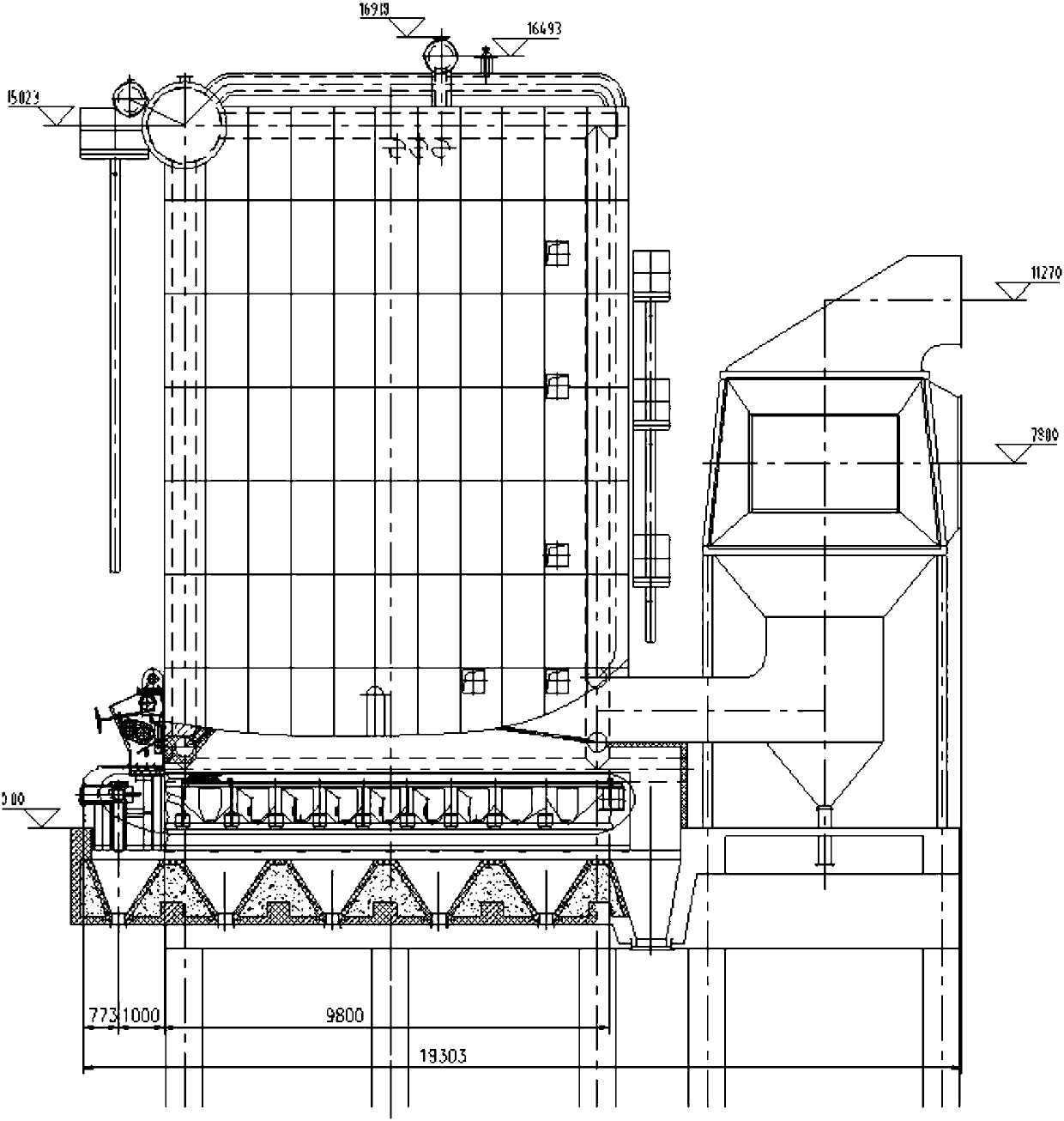
[0004] When the air preheater is applied to industrial boilers, since the boiler capacity is smaller than that of the power generation boiler and the height of the boiler is not enough, it is impossible to place the air preheater in the tail flue and adopt the vertical arrangement in which the flue gas flushes the pipe from top to bottom, as follows figure 1 As shown, in this case, in order to save space, most designers arrange the air preheater at the position where the flue gas outlet is upward at the rear of the boiler, which results in an air preheater structure in which the flue gas washes from bottom to top, but In the air preheater structure where the flue gas washes from bottom to top, because the flue gas flows upward, the ability of fine ash particles to follow the air flow is relatively good, but the ability of slightly larger ash particles to follow the air flow is poor, and they are in a vulcanized state and are easy to deposit on The surface of the tube bundle will cause ash accumulation. If the temperature of the tube wall surface is low, it is easy to cause low-temperature corrosion and the coupling effect of low-temperature corrosion and ash accumulation. In severe cases, it will cause ash blocking and even shutdown
If you want to simply create a structure in which the flue gas washes from top to bottom, it will inevitably form two 90-degree flue bends, which will increase the resistance of the flue gas

Method used


Image

  • Variable-flue-cross-section tubular air preheater
  • Variable-flue-cross-section tubular air preheater
  • Variable-flue-cross-section tubular air preheater

Examples


Embodiment Construction

[0020] The structure and working principle of the present invention will be described in detail below in conjunction with the accompanying drawings.

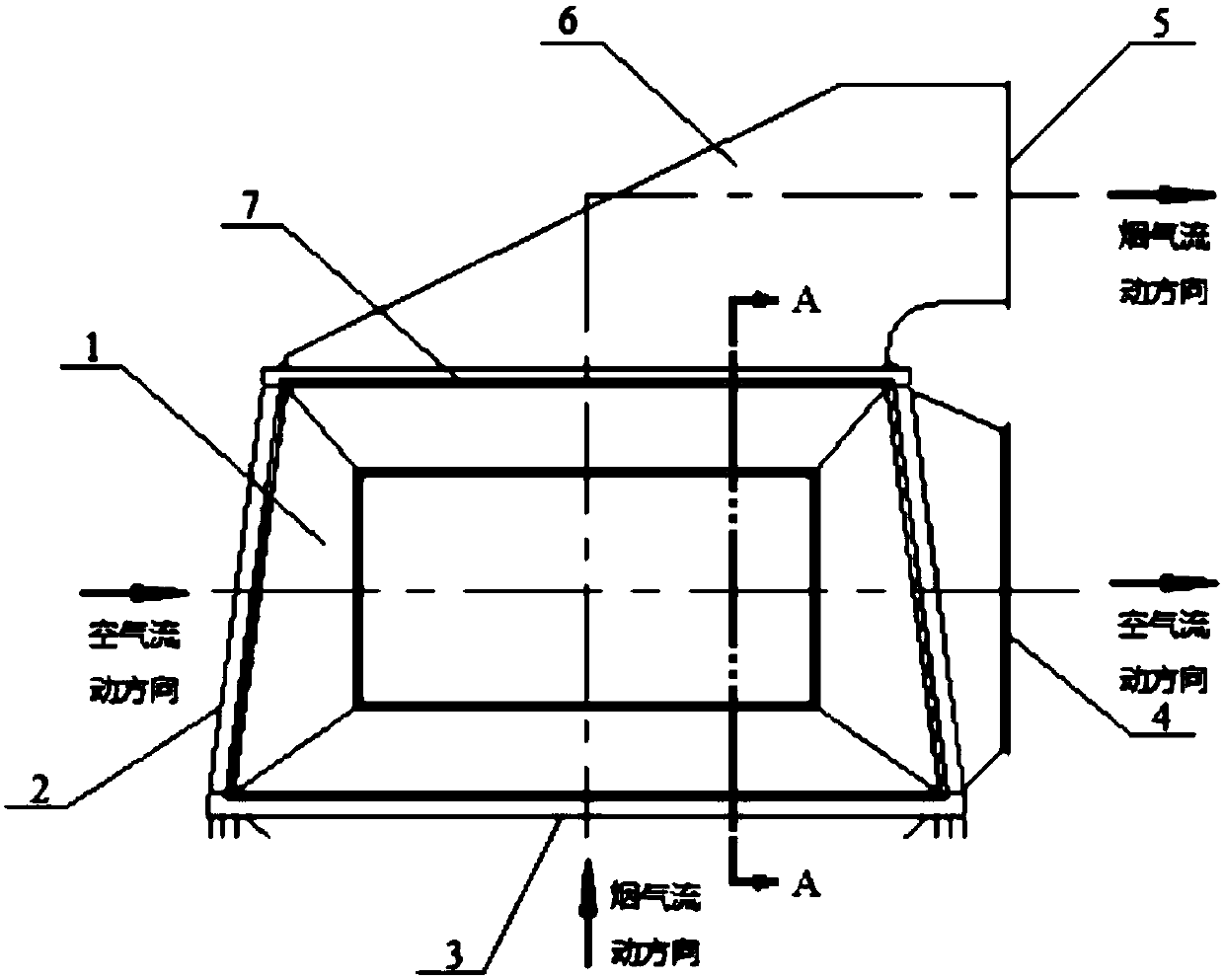
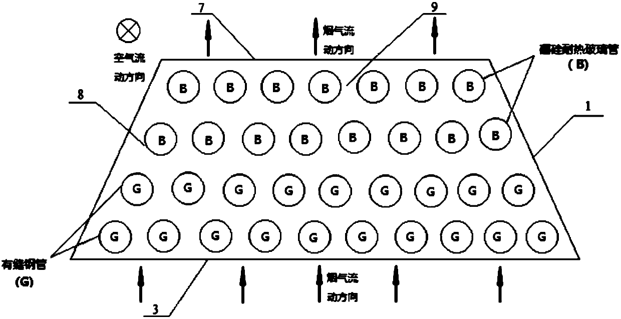
[0021] Such as figure 2 As shown, when the present invention is in use, the flue gas flows in from the flue gas inlet 3 below the air preheater shell 1, and the air flows in the heat exchange tubes 8 arranged horizontally, and the flue gas flows along the gap formed between the heat exchange tubes 8. The flue gas flow channel 9 goes up and scours the outer surface of the wall of the heat exchange tube 8 , and continuously transfers heat to the air in the heat exchange tube 8 . Specifically, the cold air to be heated flows into the air preheater shell 1 from the air inlet 2 on the left along the heat exchange tube 8, and the high-temperature flue gas flows in from the flue gas inlet 3 at the bottom of the air preheater shell 1. Going up along the flue gas flow channel 9, during this process, the outer wall of the heat exchange ...


PUM


Abstract

The invention discloses a variable-flue-cross-section tubular air preheater. The air preheater comprises an air preheater shell and adopts a horizontal arrangement mode. Smoke flows in from a lower smoke inlet and flows out from an upper smoke outlet. The outer surface of a heat exchange tube bundle horizontally arranged is scoured in the flowing process, and air flows in the heat exchange tube. Heat is continuously transferred to the air by the smoke through the wall surface of the heat exchange tube, and the flow rate of the smoke is gradually reduced with the gradual decline of the temperature of the smoke in order to prevent severe safety risk caused by dust deposition on the back surface of the heat exchange tube bundle close to the smoke outlet due to the too-large decrease of the flow rate of the smoke. By adopting the design of a constant pressure smoke flowing channel, the cross section of the smoke inlet is larger than the cross section of the smoke outlet, and the smoke flowing channel is gradually reduced, so that the smoke flow rate of the smoke outlet still can be kept larger than or equal to the smoke flow rate of the smoke inlet under the condition that the temperature of the smoke is gradually reduced. The design can increase the wall temperature of the heat exchange tube by about 10-30DEG C than a vertical arrangement mode and effectively reduce the low-temperature corrosion and dust deposition coupling function of the heat exchange tube at the smoke side.

Description

technical field [0001] The invention relates to the technical field of boiler equipment, in particular to a variable cross-section flue tube type air preheater for preventing sulfuric acid dew point corrosion and ash accumulation on the back of heat exchange tube bundles. Background technique [0002] The air preheater is a device that uses the heat of the flue gas discharged from the boiler economizer to heat the air required for combustion. It is mainly used to improve the heat exchange performance of the boiler, reduce the exhaust gas temperature, reduce heat loss and improve the working conditions of the induced draft fan. According to the materials used, air preheaters can be divided into cast iron tube air preheaters, steel pipe air preheaters, steel plate air preheaters and glass tube air preheaters, among which steel pipe air preheaters are used most widely. At present, most boilers with a steam evaporation capacity of 220t / h or below in my country use steel pipe ai...

Claims


Application Information

Patent Timeline
Patent Type & Authority Applications(China)
IPC IPC(8): F23L15/04F28D7/16F28F9/02
CPCF23L15/04F28D7/16F28F9/02Y02E20/34
Inventor 赵钦新王兴乔王云刚梁志远
Owner XI AN JIAOTONG UNIV
Learn More