Laser selective melting forming method suitable for hydraulic valve block

A technology of laser selective melting and hydraulic valves, which is applied in the field of additive manufacturing, can solve the problems of difficult manufacturing and processing of hydraulic valve blocks, difficulty in processing streamlined oil holes, and unstable dimensional accuracy, so as to meet production design requirements and be easy The effect of implementing and reducing the processing cost

Inactive Publication Date: 2018-04-03
HUAZHONG UNIV OF SCI & TECH
View PDF5 Cites 8 Cited by
  • Summary
  • Abstract
  • Description
  • Claims
  • Application Information

AI Technical Summary

Problems solved by technology

[0003] However, in recent years, with the increase in the complexity of the hydraulic system and its wide application in high-pressure and corrosive environments, more stringent requirements have been placed on the structure, strength and corrosion resistance of the hydraulic valve block, resulting in the production and manufacturing of the hydraulic valve block. There are certain difficulties in processing. For example, the oil holes inside the general hydraulic valve block can be completed by traditional processing methods, but sometimes in order to avoid mutual interference between the oil holes, process oil holes (streamlined) must be used, which increases the number of hydraulic valves. Due to the complexity of the structure of the oil hole inside the block, the traditional processing method cannot or is difficult to process such a streamlined oil hole. If the processing technology is not well considered, it will easily lead to unstable dimensional accuracy, insufficient strength, waste of raw materials, and reduced production efficiency. and high manufacturing costs

Method used


Image

  • Laser selective melting forming method suitable for hydraulic valve block

Examples


Embodiment Construction

[0023] In order to make the object, technical solution and advantages of the present invention clearer, the present invention will be further described in detail below in conjunction with the accompanying drawings and embodiments. It should be understood that the specific embodiments described here are only used to explain the present invention, not to limit the present invention. In addition, the technical features involved in the various embodiments of the present invention described below can be combined with each other as long as they do not constitute a conflict with each other.

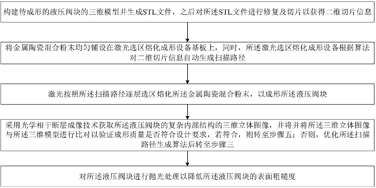
[0024] see figure 1 , the preferred embodiment of the present invention provides a laser selective melting forming method suitable for hydraulic valve blocks. The laser selective melting forming method can produce hydraulic valve blocks with complex structures and excellent performance, which can bring great benefits to the development of the national economy. benefits.

[0025] The laser sele...


PUM


Abstract

The invention belongs to the related technical field of additive manufacturing, and discloses a laser selective melting forming method suitable for a hydraulic valve block. The laser selective meltingforming method comprises the following steps that (1) a three-dimensional model of the to-be-formed hydraulic valve block is constructed, and two-dimensional slicing information is obtained; (2) laser selective melting forming equipment is laid with metal ceramic mixed powder, and a scanning path of the two-dimensional slicing information is automatically generated by the laser selective meltingforming equipment according to an algorithm; (3) layer-by-layer selective melting is conducted on the metal ceramic mixed powder by lasers according to the scanning path, and the hydraulic valve blockis formed; and (4) a three-dimensional image of a complex internal structure of the hydraulic valve block is obtained by adopting an optical coherence tomography, whether the forming quality meets design requirements or not is verified, if yes, forming is completed, and if no, the step (3) is repeated after the algorithm is generated by optimizing the scanning path. According to the laser selective melting forming method, the technological process is shortened, the cost is reduced, the economic benefit is improved, and the flexibility is high.

Description

technical field [0001] The invention belongs to the technical field related to additive manufacturing, and more specifically relates to a laser selective melting forming method suitable for hydraulic valve blocks. Background technique [0002] The hydraulic valve block is a complex functional block that installs various hydraulic components and can realize the oil circuit communication between the components in accordance with the design requirements of the existing hydraulic system schematic diagram. It is very common and very important in the hydraulic system. Components, the application range is very wide. Its use can not only simplify the design and installation steps of the hydraulic system, but also help realize the integration and standardization of the hydraulic system, thereby effectively reducing production costs and improving the stability and reliability of the hydraulic system. [0003] However, in recent years, with the increase in the complexity of the hydrau...

Claims


Application Information

Patent Timeline
Patent Type & Authority Applications(China)
IPC IPC(8): B22F3/105B33Y10/00B33Y50/00B33Y70/00
CPCB33Y10/00B33Y50/00B33Y70/00B22F10/00B22F10/36B22F10/32B22F10/66B22F10/366B22F12/17B22F10/28Y02P10/25
Inventor 文世峰胡辉魏青松周燕季宪泰吴雪良王冲史玉升
Owner HUAZHONG UNIV OF SCI & TECH
Why Eureka
Try Eureka