Energy-saving circular distributary negative pressure cleaning method

A negative pressure and cleaning technology, applied in chemical instruments and methods, solid separation, cyclone devices, etc., can solve the problems of large dust, secondary pollution of the environment, and the production of a large amount of light impurities, so as to reduce energy consumption and overall The effect of reducing mass and total power and improving the working environment

Inactive Publication Date: 2018-04-10
张存生 +1
View PDF8 Cites 7 Cited by
  • Summary
  • Abstract
  • Description
  • Claims
  • Application Information

AI Technical Summary

Problems solved by technology

like figure 1 As shown, the existing cleaning equipment generally uses a conveyor belt to send the grain to be processed to the vibrating screen 1, and the main fan 3 provides the cleaning airflow for removing impurities and mildewed light impurities, and the air is blown through the air guide frame 2. Vibrating screen 1, a large amount of light impurities and dust are produced during the cleaning process, causing secondary pollution to the environment
The disadvantage of this method is that the dust is too large and does not meet the environmental protection requirements.
Although some cleaning equipment has added a suction and dust removal device on the vibrating screen, the power of suction and dust removal is much greater than that of the main fan, and it is difficult to clean during the operation.

Method used


Image

  • Energy-saving circular distributary negative pressure cleaning method
  • Energy-saving circular distributary negative pressure cleaning method
  • Energy-saving circular distributary negative pressure cleaning method

Examples


Embodiment 1

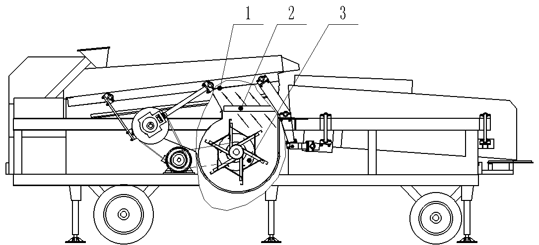
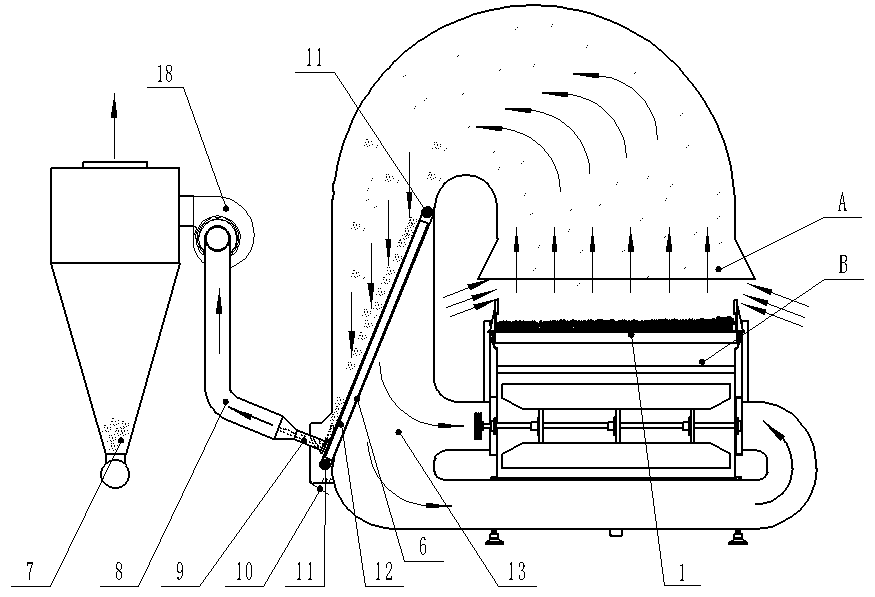
[0016] The suction nozzle in the circulation pipeline is fixed, and the filter screen rotates circularly, such as figure 2 and image 3 shown.

[0017] The main fan 3 is a cross-flow fan that provides the cleaning airflow for the cleaning equipment. The air guide frame 2 blows the cleaning airflow to the part (rectangular area) of the vibrating screen 3 to form a high-speed airflow. Different suspension heights are realized due to the difference in grain specific gravity. During the reciprocating motion of the inclined vibrating screen, different movement directions of high-quality grain, mildewed grain and light impurities are realized. High-quality grain moves upward, and mildewed grain and light impurities move downward, realizing the screening of grain and cleaning the airflow at the same time Mixed with dust and suspended impurities, it enters the circulation pipe 13 through the air inlet A, and a filter screen 6 arranged obliquely and circularly rotates is set in it to...

Embodiment 2

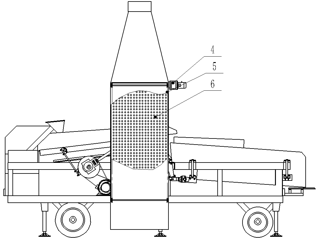
[0019] A fixed filter screen is installed in the circulating air duct, and the suction nozzle moves back and forth, such as Figure 4 and Figure 5 shown.

[0020] The difference from Example 1 lies in the dust removal method in the circulation pipeline 13. The cleaned air flow mixed with dust and suspended impurities passes through the air inlet A, enters the circulation pipeline 13, and passes through the fixed filter screen 18, which is fixed on the screen. On the support frame 12, the impurities and particles adsorbed on the fixed filter screen 18 pass through the moving suction nozzle 15 under the suction of the fan 17 and enter the Shacron dust collector 7 through the telescopic bellows 14 and the air duct 8 for processing. The processing process is the same as Same in embodiment 1, wherein mobile suction nozzle 15 is fixed on the chain of reciprocating movement and annex 5, realizes the reciprocating movement of suction nozzle 15 under the effect of sprocket wheel 11 a...


PUM


Abstract

The invention relates to the technical field of grain cleaning mechanical equipment, in particular to an energy-saving environment-friendly method for treatment processes such as impurity (including dust, grass shells) removal on grains by means of circular air flows. The method solves the problem that floating dust and light impurities fly in a cleaning process of existing grain cleaning equipment. By adopting an air flow circular blowing method, an air flow entrained with floating dust and impurities through a vibrating screen is led into an air inlet of a primary fan through a circular pipeline, a filter device is arranged in the circular pipeline, and distributary dust removal is performed through negative pressure, so that the air pressure at the air inlet of the circular pipeline iskept in a negative pressure state, and the air flow entrained with floating dust fully enters the circular pipeline and is not directly discharged to the atmosphere. By means of kinetic energy of theair flow, circulation is achieved, the total energy consumption of equipment is reduced, the air flow blown by the fan is more uniform, and the grain cleaning efficiency is improved. External cyclonedust collecting equipment is very small in power, so that dust and suspended particles in a production process are prevented from being directly discharged to the atmosphere.

Description

technical field [0001] The invention relates to the technical field of grain cleaning machinery and equipment, in particular to an energy-saving and environment-friendly method in the process of removing impurities (including dust and grass husks) from grain by using circulating airflow. Background technique [0002] Due to industry reasons, the grain cleaning site is not fixed, and some places are even in the field. Therefore, the power requirements of cleaning equipment should be as small as possible when working in the field; when used in grain depots and other places, it is required to meet the requirements of cleanliness and environmental protection. Such as figure 1 As shown, the existing cleaning equipment generally uses a conveyor belt to send the grain to be processed to the vibrating screen 1, and the main fan 3 provides the cleaning airflow for removing impurities and mildewed light impurities, and the air is blown through the air guide frame 2. For vibrating sc...

Claims


Application Information

Patent Timeline
Patent Type & Authority Applications(China)
IPC IPC(8): B07B9/00B07B7/06B07B1/46B07B11/02B04C9/00
CPCB04C9/00B07B1/4609B07B7/06B07B9/00B07B11/02
Inventor 张存生刘文俊
Owner 张存生
Why Eureka
Try Eureka