Laser 3D printing and manufacturing method of electric spark electrode
What is Al technical title?
Al technical title is built by PatSnap Al team. It summarizes the technical point description of the patent document.
A 3D printing and manufacturing method technology, applied in the direction of electrode manufacturing, manufacturing tools, electric processing equipment, etc., can solve the problems of low electrode precision, complicated process, high cost, etc., and achieve the problem of difficult forming, simple process and high reliability Effect
Inactive Publication Date: 2018-04-10
GUANGDONG INST OF NEW MATERIALS
View PDF5 Cites 12 Cited by
Summary
Abstract
Description
Claims
Application Information
AI Technical Summary
This helps you quickly interpret patents by identifying the three key elements:
Problems solved by technology
Method used
Benefits of technology
Problems solved by technology
However, due to the insufficient power of the laser involved, the complicated process, high cost, and low electrode precision, the trial production has not been successful.
Method used
Image
Click on the blue label to locate the original text in one second.
Reading with bidirectional positioning of images and text.
Examples
Embodiment 1
[0044] Weigh 5000 grams of MS1 mold steel powder, add it to the powder supply bin, and adjust the thickness of the scraper to 0.2mm;
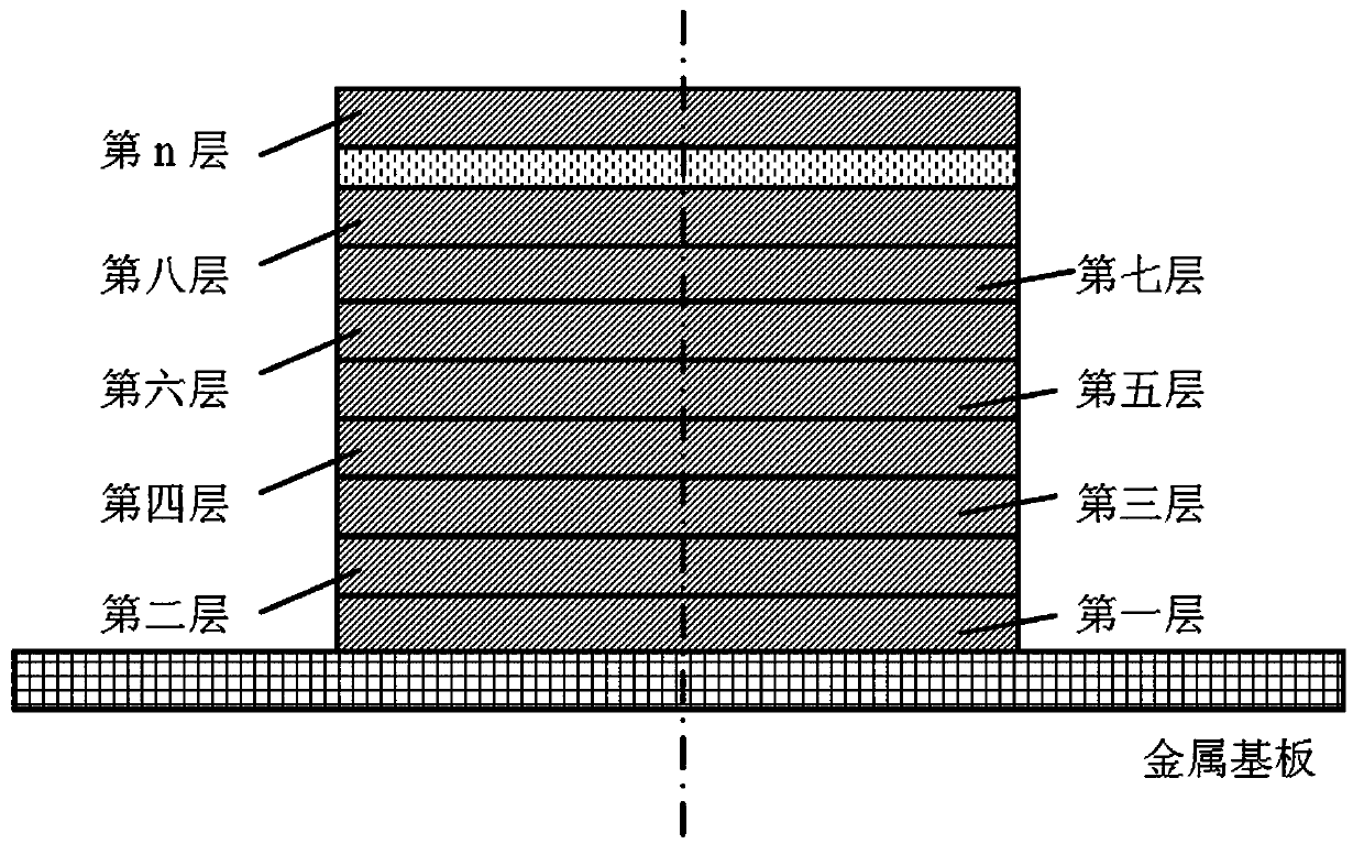
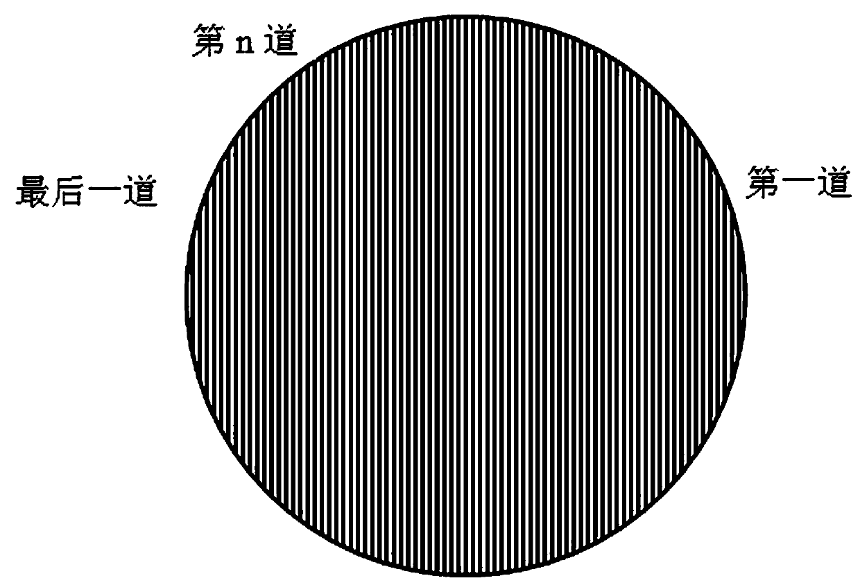
[0045] Divide the Φ3×10 electrode into 500 layers of rings, with a layer thickness of 0.02mm, and use multiple overlaps within the printing area, with an overlap rate of 50%;
[0046] The laser output power is 200W, the spot size is 0.1mm, and the cladding speed is 3000mm / s.
Embodiment 2
[0048] Weigh 1500 grams of WC powder and 3500 grams of Co-based self-fluxing alloy powder, mix well in the grinding bowl, add them to the powder supply bin, and adjust the thickness of the scraper to 0.2mm;
[0049] Divide the Φ3×10 electrode into 500 layers of rings, with a layer thickness of 0.02mm, and use multiple overlaps within the printing area, with an overlap rate of 50%;
[0050] The laser output power is 300W, the spot size is 0.1mm, and the cladding speed is 2500mm / s.
Embodiment 3
[0052] Weigh 1,500 grams of SiC powder and 3,500 grams of Ti6Al4V powder and mix them thoroughly, add them to the powder supply bin, and adjust the thickness of the scraper to 0.2mm;
[0053] Divide the Φ3×10 electrode into 500 layers of rings, with a layer thickness of 0.02mm, and use multiple overlaps within the printing area, with an overlap rate of 50%;
[0054] The laser output power is 400W, the spot size is 0.1mm, and the cladding speed is 2000mm / s.
PUM
Property
Measurement
Unit
particle size
aaaaa
aaaaa
tensile strength
aaaaa
aaaaa
Abstract
The invention discloses a laser 3D printing and manufacturing method of an electric spark electrode. The laser 3D printing and manufacturing method comprises the following steps: (1) machining and flattening a metal base plate; (2) setting a powder scraping amount of a scraper; (3) cutting a 3D design drawing of the electrode into multiple layers of slice layer structures in the height direction;(4) adjusting printing parameters of a laser device; (5) dividing each slice layer of the electrode into multiple regions, and controlling laser beams to perform overlapping scanning fusion covering in the regions covered with powder; (6) performing scanning fusion covering on the first layer of the electrode on the metal base plate, then repeatedly downwards moving the metal base plate by one slice layer thickness, and performing scanning fusion covering on the next layer of the electrode till the scanning fusion covering of the whole electrode is completed; (7) separating the metal base plate from the formed electrode to complete laser 3D printing and manufacturing of the electric spark electrode. According to the laser 3D printing and manufacturing method of the electric spark electrode, by use of a laser 3D printing technology, a metal-based material with a high content of ceramic components is directly subjected to 3D printing to form the electric spark electrode with a complicated structure, so that no molds are needed; the working procedures are simple, the production efficiency is high, and the cost is low; the manufactured electrode can meet requirements of electric sparkmachining and electric spark deposition technologies.
Description
technical field [0001] The invention relates to a method for manufacturing an electric spark electrode, in particular to a method for directly producing an electrode for surface treatment that can be used for electric sparks by using laser 3D printing metal-based powder. Background technique [0002] Electric discharge machining (EDM) technology is a special processing technology that can process conductive metal materials with almost any hardness, and has a strong use value. The principle is to use the spark corrosion phenomenon generated by the pulsed spark discharge between the tool electrode and the metal workpiece to remove the material, so as to meet the predetermined processing requirements for the size, shape and surface quality of the workpiece. Compared with mechanical processing, EDM has the advantages of no cutting force, high machining accuracy of the workpiece, and is not limited by the hardness of the material. has been widely applied. With the development o...
Claims
Application Information
Patent Timeline
Application Date:The date an application was filed.
Publication Date:The date a patent or application was officially published.
First Publication Date:The earliest publication date of a patent with the same application number.
Issue Date:Publication date of the patent grant document.
PCT Entry Date:The Entry date of PCT National Phase.
Estimated Expiry Date:The statutory expiry date of a patent right according to the Patent Law, and it is the longest term of protection that the patent right can achieve without the termination of the patent right due to other reasons(Term extension factor has been taken into account ).
Invalid Date:Actual expiry date is based on effective date or publication date of legal transaction data of invalid patent.