Optical receiving antenna based on visible light communication

An optical receiving antenna, visible light communication technology, applied in optics, optical components, condensers, etc., can solve the problems of difficult to effectively use light energy, reduced optical gain, large spot size, etc., to reduce indoor blind spots and stabilize signal-to-noise. The effect of high ratio, optical gain

Active Publication Date: 2018-04-10
FUDAN UNIV
View PDF4 Cites 4 Cited by
  • Summary
  • Abstract
  • Description
  • Claims
  • Application Information

AI Technical Summary

Problems solved by technology

The compound parabolic concentrator can gather light energy and improve the receiving power and signal-to-noise ratio of the system, but its limitation is that the optical gain decreases with the increase of the field of view, and the spot size is large and the uniformity is poor, so it is difficult to effectively use the light energy

Method used


Image

  • Optical receiving antenna based on visible light communication
  • Optical receiving antenna based on visible light communication
  • Optical receiving antenna based on visible light communication

Examples


Embodiment 1

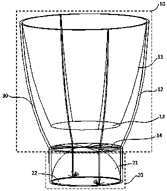
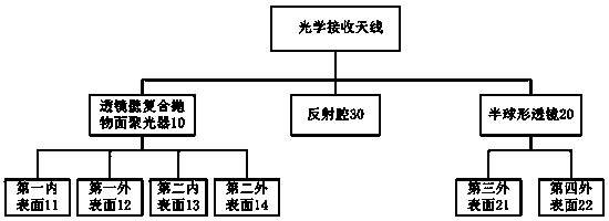
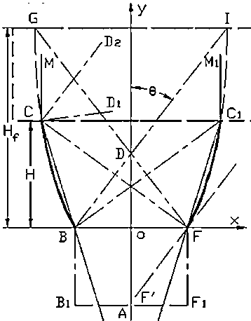
[0027] Such as figure 1 As shown, an optical receiving antenna based on visible light communication includes a lens wall compound parabolic concentrator 10 , a hemispherical lens 20 and a reflective cavity 30 . Further, as figure 2 As shown, the lens wall compound parabolic concentrator 10 includes a first inner surface 11, a first outer surface 12, a second inner surface 13 and a second outer surface 14, and a hemispherical lens 20 includes a third outer surface 21 and a fourth outer surface surface 22; further, as image 3 As shown, the basic curve of the section of the first outer surface 12 can be described by the following equation:

[0028]

[0029] In the formula , is the half field angle of the compound paraboloid structure, is the diameter of the exit port of the compound paraboloid structure, is the diameter of the entrance, f is the focal length of the parabola, is the parameter of point C, and H is the height of CPC.

[0030] by the given C and T...


PUM


Abstract

The invention discloses an optical receiving antenna based on visible light communication. The optical receiving antenna comprises a lens wall compound parabolic concentrator, a hemispherical lens anda reflection cavity. The lens wall compound parabolic concentrator comprises a first inner surface, a first outer surface, a second inner surface and a second outer surface. A cross-section curve ofthe first outer surface satisfies basic characteristics of a cross-section curve of the compound parabolic concentrator. A cross-section curve of the first inner surface is obtained after the cross-section curve of the first outer surface is rotated by an angle [delta]. The second inner surface and the second outer surface are parallel to each other. The reflection cavity is symmetrically disposedto the outer side of the first outer surface. The hemispherical lens includes a spherical surface and a fourth outer surface. The hemispherical lens is disposed below the second outer surface. The optical receiving antenna of the invention has the advantages of large viewing angle, high gain, large received power and signal-to-noise ratio, small spot size, uniform energy distribution and the like, is environmentally friendly and convenient in installation, and can meet the high-speed and stable communication requirements of an indoor visible light communication system.

Description

technical field [0001] The invention relates to the technical field of optical antennas, in particular to an optical receiving antenna based on visible light communication. Background technique [0002] Visible light communication technology, as an emerging wireless communication technology that uses LED light-emitting devices to emit high-speed bright and flickering light signals that are imperceptible to the human eye to achieve information transmission, compared with traditional radio frequency communication and other optical wireless communication methods, visible light communication has not Limited by bandwidth, free from electromagnetic interference of electronic equipment, high security and confidentiality, and LED lighting communication equipment is easy to install, so it has great development potential. [0003] At present, the main research areas of indoor visible light communication technology include communication channel model, modulation and demodulation techno...

Claims


Application Information

Patent Timeline
Patent Type & Authority Applications(China)
IPC IPC(8): G02B17/08G02B19/00
CPCG02B17/0868G02B19/0028
Inventor 孔令豹彭星
Owner FUDAN UNIV
Why Eureka
Try Eureka