An interleaving-based capacitor clamped high-gain boost converter

A boost converter and capacitor clamping technology, which is applied in the direction of adjusting electrical variables, output power conversion devices, DC power input conversion to DC power output, etc., can solve the problem of large device stress, large inductor volume, and large number of devices, etc. problem, to achieve the effect of low device voltage stress, small input current ripple, and high gain

Active Publication Date: 2018-04-10
BEIJING JIAOTONG UNIV
View PDF7 Cites 11 Cited by
  • Summary
  • Abstract
  • Description
  • Claims
  • Application Information

AI Technical Summary

Problems solved by technology

However, there are still some problems in various related technologies that mention the interleaved parallel Boost structure, such as low gain, excessive device stress, excessive number of devices, and large inductor volume. Therefore, in order to achieve a simple structure and With high gain characteristics, the topology based on the interleaved parallel Boost structure still needs further research and development

Method used


Image

  • An interleaving-based capacitor clamped high-gain boost converter
  • An interleaving-based capacitor clamped high-gain boost converter
  • An interleaving-based capacitor clamped high-gain boost converter

Examples


Embodiment Construction

[0060] Embodiments of the present invention are described in detail below, examples of which are shown in the drawings, wherein the same or similar reference numerals designate the same or similar elements or elements having the same or similar functions throughout. The embodiments described below by referring to the figures are exemplary and are intended to explain the present invention and should not be construed as limiting the present invention.

[0061] The following describes the interleaved parallel capacitor-clamped high-gain boost converter based on the embodiments of the present invention with reference to the accompanying drawings.

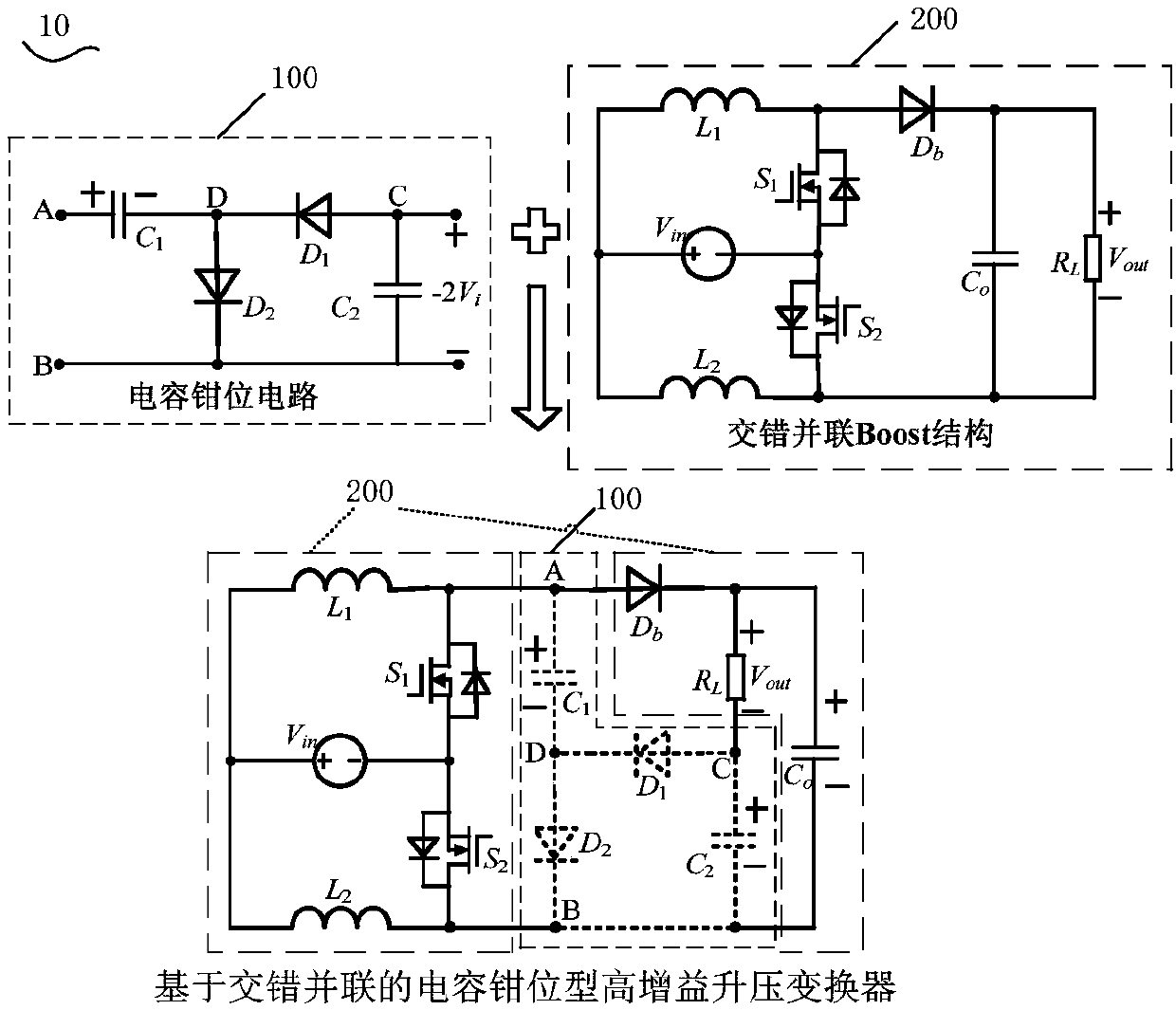
[0062] figure 1 It is a schematic diagram of generating a circuit structure of a capacitor-clamped high-gain boost converter based on an interleaved parallel connection according to an embodiment of the present invention.

[0063] like figure 1 As shown, the capacitor-clamped high-gain boost converter 10 based on interleaved parallel ...


PUM


Abstract

The invention provides an interleaving-based capacitor clamped high-gain boost converter comprising a capacitor clamped circuit and an interleaving Boost structure which comprises a first inductor, asecond inductor, a first switch tube, a second switch tube, a main diode, a main capacitor, an input source and a load. The interleaving Boost structure is connected with the capacitor clamped circuitvia a first node, a second node and a third node to generate three-level square waves which are connected to the capacitor clamped circuit, so that a clamping capacitor can obtain a backward voltagetwo times an output voltage of the interleaving Boost structure; the clamping capacitor is embedded to a negative terminal of the load to obtain a boost converter topology with the gain being 3/(1-D).The converter has the advantages that clamping capacitance generated during work of the capacitor clamped circuit can be organically fused in the interleaving Boost structure, so that the boost converter has the advantages of high gain, small input current ripples and low voltage stress of devices.

Description

technical field [0001] The invention relates to the technical field of power electronics, in particular to a capacitor-clamped high-gain boost converter based on an interleaved parallel connection. Background technique [0002] At present, high-efficiency, low-cost, safe and reliable power conversion for the electric energy output by photovoltaic cells, so that it can be connected to the large power grid or micro-grid more efficiently and stably, is a very key technical link of photovoltaic power generation, and has been widely recognized and adopted. The photovoltaic access power conversion system includes the front-stage DC converter and the back-stage grid-connected inverter. The output voltage of the current photovoltaic cell single board is low, and the voltage is 20-50V. Therefore, a DC converter with high voltage gain is required to generate a higher voltage for grid-connected inverters, DC micro-grids, and high-voltage DC loads. At the same time, as industrial appli...

Claims


Application Information

Patent Timeline
Patent Type & Authority Applications(China)
IPC IPC(8): H02M3/158
CPCH02M3/1584Y02E10/56
Inventor 李虹曾洋斌张晓超郝瑞祥郑琼林孙湖
Owner BEIJING JIAOTONG UNIV
Why Eureka
Try Eureka