Ceramic filter capable of cleaning ceramic fan blades

A ceramic filter and fan blade technology, which is applied in filtration and separation, moving filter element filters, separation methods, etc., can solve the problems of limited adsorption capacity and increase maintenance costs, so as to increase maintenance costs, reduce pipe diameter, and improve cleaning. The effect of efficiency

Inactive Publication Date: 2018-04-13
成都龙泉马龙机械厂
View PDF0 Cites 0 Cited by
  • Summary
  • Abstract
  • Description
  • Claims
  • Application Information

AI Technical Summary

Problems solved by technology

[0005] The present invention aims at removing the impurities on the ceramic fan blades by adsorbing them in the slurry pool, and the adsorption capacity is limited, and the impurities between some adjacent ceramic fan blades cannot be well eradicated and can only be maintained when the equipment is shut down. Cleaning from time to time increases the maintenance cost and provides a ceramic filter that can clean the ceramic fan blades

Method used


Image

  • Ceramic filter capable of cleaning ceramic fan blades
  • Ceramic filter capable of cleaning ceramic fan blades
  • Ceramic filter capable of cleaning ceramic fan blades

Examples


Embodiment 1

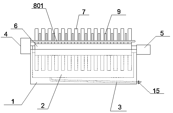
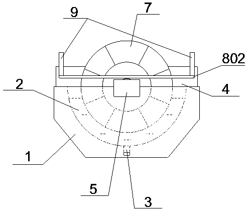
[0031] like Figure 1 to Figure 2 As shown, the ceramic filter capable of cleaning ceramic fan blades includes a drum 6, a motor 5, and a base 1. The base 1 is provided with a slurry pool 2, the drum 6 is connected to the motor 5, and half of the drum 6 is immersed in the slurry pool 2. Multiple groups of ceramic fan blades 7 are evenly spaced on the drum 6 , and the motor 5 is located at one end of the base 1 . The other end of the base 1 is provided with a water tank 4, and the water tank 4 is connected with a water delivery pipe. The water delivery pipe is a closed-loop structure, and the water delivery pipe includes a first horizontal section 801, a second horizontal section 802 and a third horizontal section connected in sequence. The first horizontal section Section 801 and the third horizontal section are parallel to the long side of the base 1, and the first horizontal section 801 and the third horizontal section are located above the base 1, and the first horizontal s...

Embodiment 2

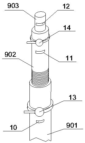
[0034] Based on Example 1, such as image 3 As shown, the water spray pipe 9 includes a first water spray pipe 901, a second water spray pipe 902 and a third water spray pipe 903 from bottom to top, the first water spray pipe 901 is provided with a first water outlet 10, and the second water spray pipe 901 The water pipe 902 is provided with a second water outlet 11, and the third water spray pipe 903 is provided with a third water outlet 12, and the opening sizes of the first water outlet 10, the second water outlet 11 and the third water outlet 12 increase sequentially, And the opening directions all face the drum 6 .

Embodiment 3

[0036] Based on Embodiment 2, the lower part of the second water spray pipe 902 is provided with threads, and the lower part of the second water spray pipe 902 extends into the first water spray pipe 901 and is connected with the first water spray pipe 901 through threads.


PUM


Abstract

The invention relates to the field of water treatment for mechanical processing, specifically a ceramic filter capable of cleaning ceramic fan blades. The technical points are: including a drum, a motor and a base, the motor is located at one end of the base, and the other end of the base is provided with a water tank , the water tank is connected with a water pipe, the water pipe is a closed-loop structure, the water pipe includes the first horizontal section, the second horizontal section and the third horizontal section connected in sequence, the first horizontal section and the third horizontal section are parallel to the base length The sides are parallel. The first horizontal section and the third horizontal section are located on the base and symmetrically provided with water spray pipes, the second horizontal section is parallel to the short side of the base and on the same side as the motor, and the drum is located in the closed loop of the water delivery pipe. It solves the problem that most of the existing ceramic filters remove the impurities on the ceramic fan blades by adsorbing them in the slurry tank. The adsorption capacity is limited, and the impurities between some adjacent ceramic fan blades cannot be well eradicated. Only when the equipment is shut down for maintenance Cleaning up the problem raised maintenance costs.

Description

technical field [0001] The invention relates to the field of machining water treatment, in particular to a ceramic filter capable of cleaning ceramic fan blades. Background technique [0002] Ceramic filter is a kind of dehydration equipment, mainly composed of ceramic filter plate, roller system, mixing system, ore supply and discharge system, vacuum system, filtrate discharge system, scraping system, backwashing system, combined cleaning ultrasonic cleaning, automatic acid mixing It is composed of cleaning system, automatic control system, tank body and frame. [0003] In the field of ore pulp processing, during the process of filtering and desizing, ore accumulation often occurs in the tank of the ceramic filter, resulting in increased resistance and press stop accidents; and there are problems such as the wear of the stirring bearing, the overload of the motor, and the easy deformation of the stirring parts. . Most of the impurities adsorbed on the ceramic fan blades a...

Claims


Application Information

Patent Timeline
Patent Type & Authority Applications(China)
IPC IPC(8): B01D33/17B01D33/50B01D33/80
CPCB01D33/17B01D33/503B01D33/80
Inventor 李成
Owner 成都龙泉马龙机械厂
Why Eureka
Try Eureka