Chemical test tube cleaning device

A technology for cleaning devices and test tubes, applied in the field of chemical utensils, can solve the problems of low work efficiency, skin and human body damage, time-consuming and laborious, etc., and achieve the effect of improving efficiency and preventing test tubes from being broken.

Inactive Publication Date: 2018-04-13
新昌县中申制冷配件厂
View PDF0 Cites 11 Cited by
  • Summary
  • Abstract
  • Description
  • Claims
  • Application Information

AI Technical Summary

Problems solved by technology

[0002] The instrument commonly used in the test tube chemistry laboratory is used as a reaction container for a small amount of reagents. It is used at room temperature or under heating. The test tubes are divided into ordinary test tubes, test tubes with branches, centrifugal test tubes and other test tubes. For the next use, the cleaning of the test tubes after use has become the biggest problem. The chemical test tube cleaning devices in the prior art have low working efficiency and are difficult to meet the cleaning requirements, and it is difficult to realize efficient and batch cycle cleaning of the chemical test tubes. At present, most of them are It is manual cleaning, but most of the chemicals are acidic and alkaline, which will cause certain damage to the skin and human body, and the cleaning effect is not good, so the test tube cannot be cleaned evenly. After cleaning, there will be a lot of water stains on the test tube. It needs to be dried manually, which is time-consuming and labor-intensive. If it is not cleaned, it will have a certain impact on the next experiment

Method used


Image

  • Chemical test tube cleaning device

Examples


Embodiment Construction

[0017] The following will clearly and completely describe the technical solutions in the embodiments of the present invention with reference to the accompanying drawings in the embodiments of the present invention. Obviously, the described embodiments are only some, not all, embodiments of the present invention.

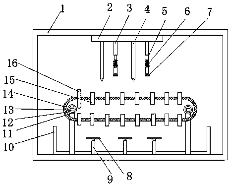
[0018] refer to figure 1 , a cleaning device for chemical test tubes, comprising a bracket 1, the bracket 1 is a cavity structure, a fixed plate 2 is horizontally installed at the upper side wall of the inner side of the bracket 1, and the installation time at the lower side wall of the fixed plate 2 is The controller and the inductor are connected with the motor 13 in parallel circuit, the control button is installed at the side wall of the outer end of the support 1, the inside of the fixed plate 2 is provided with a through hole, and the upper end communicates with the through hole provided inside the support 1 and is connected to The water pipe 4 installed at the...


PUM


Abstract

The invention discloses a cleaning device for chemical test tubes, which comprises a bracket, a fixed plate is installed at the upper end of the bracket, a water pipe is installed at the lower end of the fixed plate, a suspension rod is installed on one side of the water pipe, and a telescopic rod is arranged inside the suspension rod. The upper end of the telescopic rod is installed with a connecting ring to connect with a spring, the spring is connected to one side of the telescopic rod installed inside the suspension rod, a brush is installed at the bottom of the suspension rod, a water tank is arranged at the bottom of the inner cavity of the bracket, and a support rod is installed inside the water tank Connect the shaft sleeve installed on the upper end, the motor is installed inside the shaft sleeve, the motor rotating shaft, the upper end of the rotating shaft is installed with a transmission belt, the upper end of the transmission belt is provided with a test tube hole inside, the test tube is installed inside the test tube hole, and one side of the support column is installed The shaft sleeve is equipped with fan blades on the left and right sides of the shaft sleeve. In the present invention, the test tubes are installed in the conveyor belt and transported to the lower end of the water pipe. After the test tubes are cleaned, the fans are used to dry them. The structure is simple and the operation is convenient.

Description

technical field [0001] The invention relates to the technical field of chemical appliances, in particular to a cleaning device for chemical test tubes. Background technique [0002] The instrument commonly used in the test tube chemistry laboratory is used as a reaction container for a small amount of reagents. It is used at room temperature or under heating. The test tubes are divided into ordinary test tubes, test tubes with branches, centrifugal test tubes and other test tubes. For the next use, the cleaning of the test tubes after use has become the biggest problem. The chemical test tube cleaning devices in the prior art have low working efficiency and are difficult to meet the cleaning requirements, and it is difficult to realize efficient and batch cycle cleaning of the chemical test tubes. At present, most of them are It is manual cleaning, but most of the chemicals are acidic and alkaline, which will cause certain damage to the skin and human body, and the cleaning ...

Claims


Application Information

Patent Timeline
IPC IPC(8): B08B9/32B08B9/36F26B15/18F26B21/00
CPCB08B9/32B08B9/0821B08B9/36B08B2209/08F26B15/18F26B21/004
Inventor 张海东
Owner 新昌县中申制冷配件厂
Why Eureka
Try Eureka