Large-specification deep hole boring device

A large-scale, deep-hole technology, applied in the field of large-scale deep-hole boring devices, can solve the problem that the deep-hole boring head is difficult to process discontinuous holes and soft material holes, the boring diameter of the deep-hole boring head cannot be adjusted arbitrarily, and the processing hole diameter is difficult. Large and other problems, to achieve the effect of compact coaxial installation structure, wide processing range and easy finishing

Pending Publication Date: 2018-04-13
德州普利森机床有限公司
View PDF0 Cites 2 Cited by
  • Summary
  • Abstract
  • Description
  • Claims
  • Application Information

AI Technical Summary

Problems solved by technology

[0002] For the boring processing of inner holes, usually, for holes with a ratio of hole depth to diameter ≤ 5, it is directly completed with a conventional boring machine; for holes with a depth-to-diameter ratio > 5, it is usually realized by deep hole boring; In actual production applications, a large part of them are deep-hole workpieces with a depth-to-diameter ratio of 5 to 12. This type of workpiece is a non-oil cylinder workpiece, and the machining hole diameter is too large, and many of these workpiece holes are discontinuous. Holes, such as the inner hole of the roller of papermaking machinery, the inner hole of the large winch roller, the inner hole of the large motor shell, the inner hole of the chemical machinery shell, the inner hole of the pressure vessel shell, etc. There are many problems in processing the above workpieces with the traditional deep hole processing method : If a corresponding large boring head must be designed, and the boring diameter of the deep hole boring head cannot be adjusted at will; due to the existence of the guide key, it is very difficult for the deep hole boring head to process discontinuous holes and soft material holes; the combination of rigid boring bar + boring head The structure makes the feed distance must be greater than 2 times the processing length to satisfy the feeding and retracting, resulting in long bed body and high overall manufacturing cost

Method used


Image

  • Large-specification deep hole boring device
  • Large-specification deep hole boring device
  • Large-specification deep hole boring device

Examples


Embodiment Construction

[0031] The technical solutions of the present invention will be clearly and completely described below in conjunction with the accompanying drawings of the present invention.

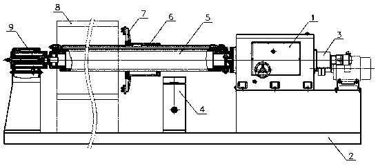
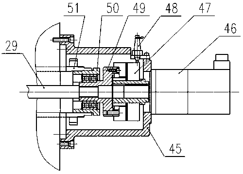
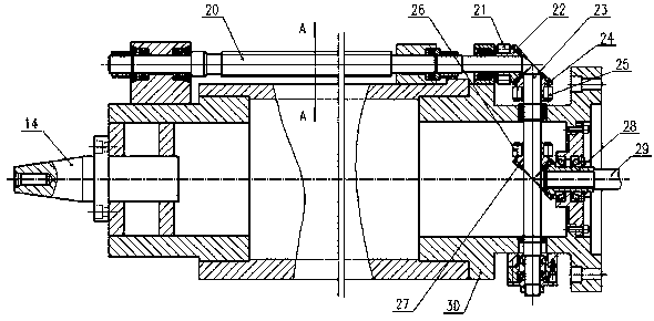
[0032] As shown in the figure, the large-scale deep hole boring device adopts a fairly rigid boring bar 5 as a whole, which passes through the inner hole of the workpiece 8, and one end of the boring bar 5 is installed in the boring bar box through a flange. On the main shaft 51, the power input is realized, and the other end is connected to the tailstock 9, so as to realize the simply supported state at both ends of the boring bar; The frame 31 is a long structure, the sliding body 6 moves along the boring bar 5 as a whole, and is guided relative to the boring bar 5 through the screw bracket 31; the cutter head 7 is installed above the sliding body 6, and the cutter head 7 is installed symmetrically A pair of cutters 44, the size of the cutters 44 is corrected according to the machining aperture, and t...


PUM


Abstract

The invention relates to a large-scale deep hole boring device, which includes a base plate, a feeding device, a boring bar box, a boring bar bracket, a boring bar, a sliding body, a cutter head, a workpiece and a tailstock. The boring bar passes through the inner hole of the workpiece. One end of the boring bar is connected to the boring bar box, and the other end is connected to the tailstock. The boring bar bracket is located at the lower part of the boring bar. A feed screw and a slider are installed above the boring bar. The slider is installed on the feed screw. The sliding body moves back and forth on the boring bar along the feed screw; the sliding body is equipped with a cutter head, and a transmission shaft is installed in the boring bar box. One end of the transmission shaft is connected with the feeding device, and the other end is connected with the end of the boring bar. The transmission shaft can drive the boring bar to rotate as a whole, and when the boring bar rotates, it can drive the feed screw to rotate, so that the sliding body on it can move back and forth relative to the boring bar; the overall structure of the device is compact, and the manufacturing cost is low. Boring bars of different specifications are used within a certain range, with high machining accuracy and wide application range, which can meet the needs of various working conditions.

Description

technical field [0001] The invention belongs to the field of mechanical processing and machine tool equipment, and in particular relates to a large-size deep hole boring device. Background technique [0002] For the boring processing of inner holes, usually, for holes with a ratio of hole depth to hole diameter ≤ 5, conventional boring machines are used directly; for holes with a depth-to-diameter ratio > 5, deep hole boring is usually used; In actual production applications, a large part of them are deep-hole workpieces with a depth-to-diameter ratio between 5 and 12. This type of workpiece is a non-oil cylinder workpiece, and the machining hole diameter is too large, and many of these workpiece holes are discontinuous. Holes, such as the inner hole of the roller of papermaking machinery, the inner hole of the large winch roller, the inner hole of the large motor shell, the inner hole of the chemical machinery shell, the inner hole of the pressure vessel shell, etc. Ther...

Claims


Application Information

Patent Timeline
Patent Type & Authority Applications(China)
IPC IPC(8): B23B41/02
CPCB23B41/02
Inventor 鲁绪阁任传文贾强朱玉华黄居河齐鹏陈凯吕桂柱郭凝华
Owner 德州普利森机床有限公司
Why Eureka
Try Eureka