Multifunctional numerical control turn milling combined machine tool

A combined machine tool, multi-functional technology, applied to other manufacturing equipment/tools, manufacturing tools, etc., can solve the problems of single turning or milling function, high price, etc., and achieve the effect of reducing floor space and saving investment

Pending Publication Date: 2018-04-13
SHANDONG LUNAN MACHINE TOOL
0 Cites 3 Cited by

AI-Extracted Technical Summary

Problems solved by technology

[0002] Existing CNC lathes or CNC milling machines only have a single turning or milling function. Due to the high system requirements and high price of the turning-milling compound machine tools currently on th...

Method used

The present invention grafts together a flat bed numerically controlled lathe and a numerically controlled milling machine, has two servo main shafts, four feed shafts, can respectively carry out turning, milling, turning and milling, grinding, drilling, stranding, Boring function. This machine tool is equipped with a brake function component on the lathe ...

Abstract

The invention discloses a multifunctional numerically controlled turning and milling combined machine tool, which provides a kind of turning, milling, grinding, drilling, reaming, turning and milling, boring, threading, which is suitable for small vulnerable parts of ship equipment and remanufacturing and repairing parts. Machine tools for tapping and other processing. In order to achieve the above object, the technical scheme adopted by the present invention is as follows. Including the base, the front of the base is equipped with a lathe bed, one end of the lathe bed is equipped with a lathe headstock, and the other end is equipped with a tailstock; the rear of the base is equipped with a guide rail parallel to the lathe bed, and a guide rail is installed along the lathe bed Moving milling column. Since the present invention is formed by grafting a CNC lathe and a CNC milling machine, the machine tool has all the functions of the lathe and the milling machine, and adopts the domestic lathe CNC system; the functions of the two machine tools are completed on one machine tool, which reduces the footprint of the equipment , saving investment.

Application Domain

Other manufacturing equipments/tools

Technology Topic

Numerical control systemEngineering +3

Image

  • Multifunctional numerical control turn milling combined machine tool
  • Multifunctional numerical control turn milling combined machine tool

Examples

  • Experimental program(1)

Example Embodiment

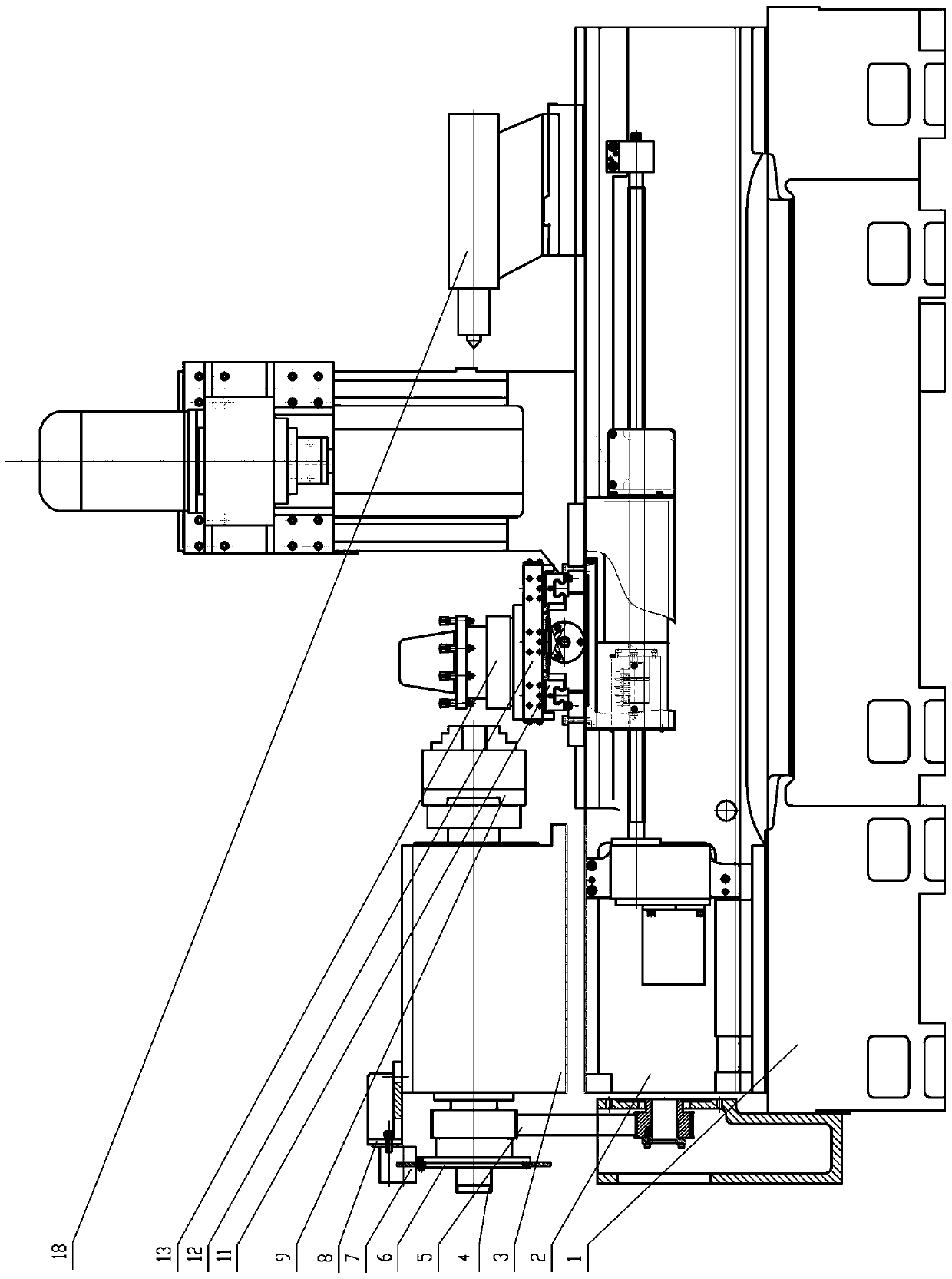
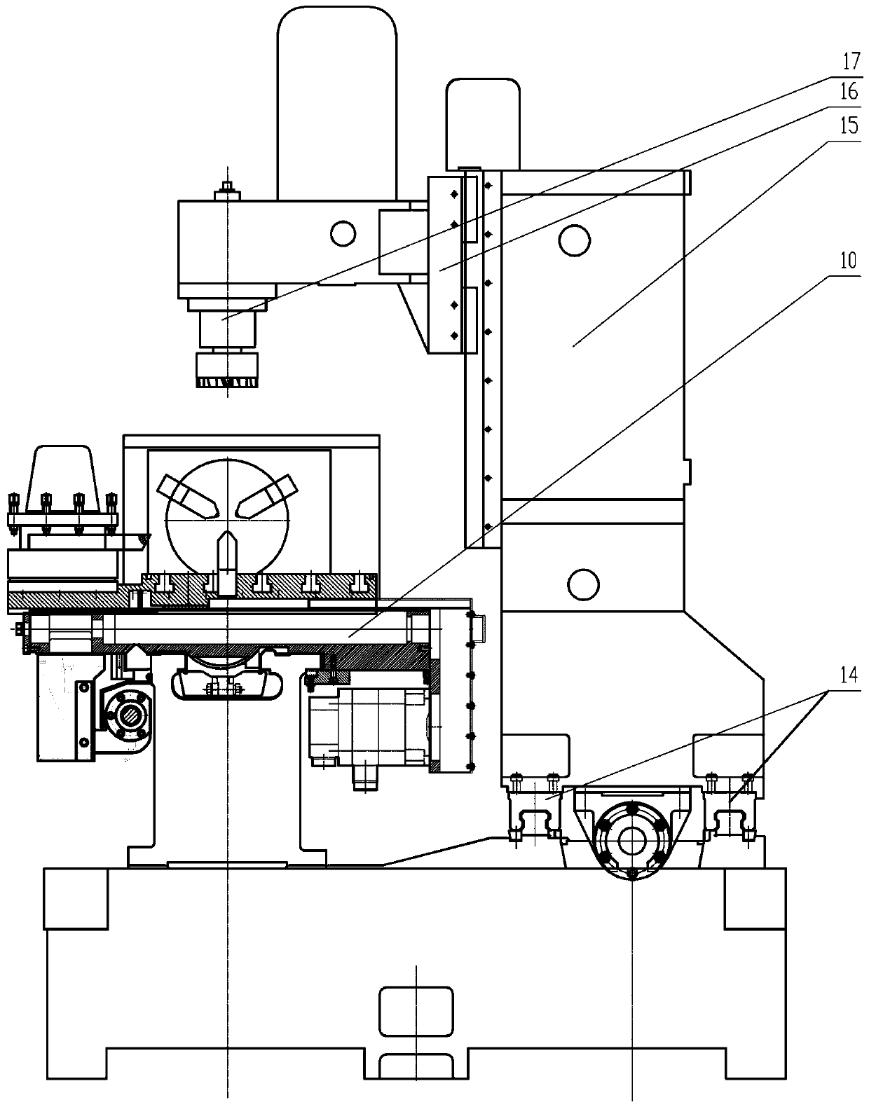
[0017] Attached below Figure 1-2 The present invention will be further explained.
[0018] Such as figure 1 As shown, the present invention fixes the flat bed CNC lathe at the front of the base, and the CNC milling machine column is installed at the back of the base and can move left and right. Both "front" and "rear" refer to the "front" at the end closer to the operator and the "rear" at the far end relative to the operator. A milling machine headstock 16 is installed on the column to move up and down. This device adopts the lathe numerical control system to control the movement of two main shafts and four feed axes, and realizes multiple functions such as turning, milling, grinding, drilling, reaming, turning and milling.
[0019] Such as figure 1 Shown. A multifunctional CNC turning-milling combined machine tool structure includes a base 1, a lathe bed 2 is installed at the front of the base 1, a lathe headstock 3 is installed at the left end of the lathe bed 2, and a tailstock 18 is installed at the right end of the lathe bed. A lathe spindle 4 is installed in the lathe spindle box 3.
[0020] The main shaft of the lathe is connected with the first servo motor through a timing belt 5. The rear end of the lathe spindle is provided with a brake disc 6, and the spindle box of the lathe is also provided with a brake 7 and a brake support 8 that cooperate with the brake. The brake 7 is fixed on the spindle box of the lathe through the brake support 8. A chuck 9 is installed at the other end (right end) of the lathe spindle. The horizontal guide rail of the lathe bed 1 is equipped with a large slide 10 that moves along the direction of the bed, and a small guide 11 is installed on the large slide 10. A working table 12 is installed on the small guide rail 11, and an electric turning tool holder 13 is installed on the working table 12. The electric turning tool post 13 can realize the feed in the left and right directions and the front and rear directions through the combined movement of the large slide and the small guide rail. A T-shaped groove is provided on the workbench 12 to facilitate the clamping of the workpiece by the clamp.
[0021] Such as figure 2 As shown, at the rear of the base 1, two guide rails 14 parallel to the bed of the lathe are installed on the other side of the large carriage 10. A milling machine column 15 that moves along the lathe bed 2 direction is installed on the guide rail, a vertical guide rail is installed on the milling machine column 15, and a milling machine headstock 16 that moves vertically up and down along the milling machine column is installed on the guide rail. The milling machine spindle box 16 is equipped with a milling machine spindle 17, and the milling machine spindle 17 is directly connected to the second servo motor through a timing belt. The milling machine spindle 17 has up and down movement, and the milling machine column 15 moves along the guide rail to realize the left and right sliding of the worktable 12, which can complete the vertical, horizontal and vertical movement of the workpiece to complete the milling operation.
[0022] The application description of the present invention is as follows.
[0023] The invention grafts a flat bed numerically controlled lathe and a numerically controlled milling machine. It has two servo spindles and four feed shafts, which can perform turning, milling, turning and milling, grinding, drilling, twisting and boring functions respectively. This machine tool is equipped with a brake function component on the lathe spindle, which can better control the rotation and exact stop of the spindle. It adopts a domestic lathe servo control system, which is low in price and greatly saves equipment investment. It is very suitable for small vulnerable parts and their remanufacturing repair Multifunctional machining of parts such as turning, milling, drilling, and reaming.
[0024] The above-mentioned embodiments only describe the preferred embodiments of the present invention, and do not limit the concept and protection scope of the present invention. Under the premise of not departing from the design concept of the present invention, those of ordinary skill in the art will understand the technology of the present invention. Various modifications and improvements made in the scheme should fall within the protection scope of the present invention.

PUM

no PUM

Description & Claims & Application Information

We can also present the details of the Description, Claims and Application information to help users get a comprehensive understanding of the technical details of the patent, such as background art, summary of invention, brief description of drawings, description of embodiments, and other original content. On the other hand, users can also determine the specific scope of protection of the technology through the list of claims; as well as understand the changes in the life cycle of the technology with the presentation of the patent timeline. Login to view more.

Similar technology patents

Betel nut packing machine

ActiveCN105270678ASmall footprintreduce noise
Owner:KUNSHAN BAIAO INTELLIGENT EQUIP CO LTD

Portable wetlands

InactiveUS20080179240A1high surface areasmall footprint
Owner:KAUPPI FREDERICK J +2

Classification and recommendation of technical efficacy words

  • Small footprint
  • less investment

Split-flow rectisol device

Owner:SHANGHAI INT ENG CONSULTING

Production of cold rolling high-strength ultra-deep-drawing steel plate by bell-type furnace and method for manufacturing same

InactiveCN101135025AHigh resistance to secondary processing brittlenessless investment
Owner:BAOSHAN IRON & STEEL CO LTD
Why Eureka
Try Eureka