

Oilfield produced water treatment device
A treatment device and technology for produced water, which is applied in water/sewage treatment, flotation water/sewage treatment, multi-stage water/sewage treatment, etc. It can solve the problems of inability to adapt to raw water quality fluctuations, unsatisfactory treatment effects, and complicated treatment methods, etc. problem, to achieve fast connection, fast commissioning, and guaranteed processing effect
- Summary
- Abstract
- Description
- Claims
- Application Information
AI Technical Summary
Problems solved by technology
Method used
Image

Examples
Embodiment Construction
[0018] The present invention will be described in detail below in conjunction with the accompanying drawings and specific embodiments.
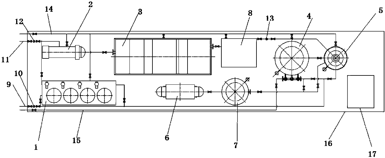
[0019] A kind of oilfield production water treatment device of the present invention, as figure 1 As shown, it includes a dosing device 1 , a cyclone separator 2 , an air flotation device 3 , an oil-water separation filter 5 and a sintered tube fine filter 4 which are sequentially connected by pipelines.
[0020] It also includes an air source system, which is respectively connected to the sintered tube fine filter 4 and the oil-water separation filter 5 through pipelines, and the air source system provides a power source for the pneumatic valve system.
[0021] It also includes a container 16, which is heat-insulated to adapt to cold and harsh conditions; dosing device 1, cyclone separator 2, air flotation device 3, sintered tube fine filter 4, oil-water separation filter 5 , air compressor 6 and gas storage tank 7 are all installed on the ...
PUM
 Abstract
Description
Claims
Application Information