Pipe bending machine

A pipe bending machine and pipe bending technology, which is applied in the directions of forming tools, feeding devices, positioning devices, etc., can solve the problems that the pipe bend is not tightly clamped, the pipe fittings are not clamped tightly, and the axial direction of the guide cavity is not parallel to the axial direction. Achieve the effect of improving the quality of elbows, ensuring stability, and ensuring parallelism

Pending Publication Date: 2018-04-17
浙江长兴和良智能装备有限公司
View PDF13 Cites 5 Cited by
  • Summary
  • Abstract
  • Description
  • Claims
  • Application Information

AI Technical Summary

Problems solved by technology

Since the clamping mold is installed on the clamping mold base 31 using a dovetail keyway structure, it is convenient for the assembly connection between the two and the fixed connection through bolts; however, when the verticality between the bottom surface of the clamping mold base and the clamping mold installation surface is not good or the When the parallelism between the mounting surface of the mold and the clamping surface is not good, it is difficult to ensure that the clamping end surface of the clamping mold is arranged parallel to the clamping end surface of the round mold, that is, it is difficult to ensure that the axis of the clamping cavity and the axis of the circular cavity are arranged in parallel, so that The clamping cavity and the round cavity are in the shape of a bell mouth, which leads to the problem of slipping when the clamp is not tight when bending the pipe, and it is difficult to ensure the quality of the bending pipe
[0004] Publication number is disclosed in the patent document of CN10

Method used


Image

  • Pipe bending machine
  • Pipe bending machine
  • Pipe bending machine

Examples


Embodiment 1

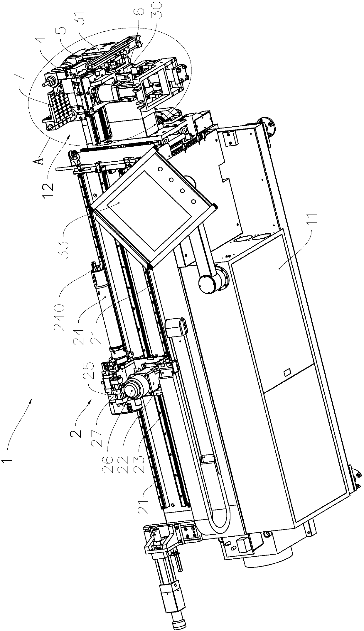
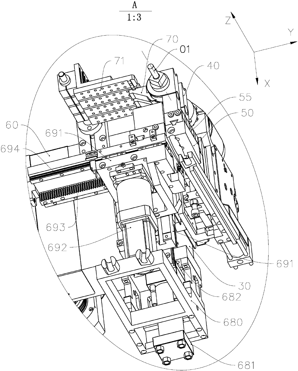
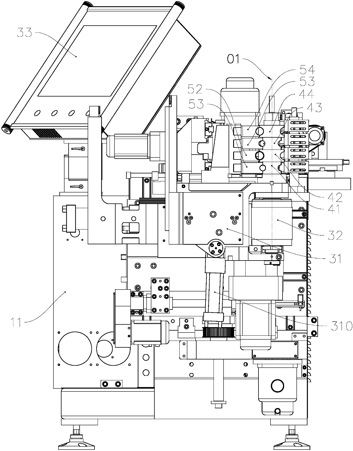
[0036] see Figure 1 to Figure 7 , The pipe bender 1 of the present invention is a numerical control pipe bender, including a frame 11, a control unit, a machine head 12 and a feeding trolley 2 installed on the frame 11 and controlled by the control unit. The machine head 12 includes a mounting seat 30, a swing arm 31, a round die assembly 4, a clamping die assembly 5, a mold guide unit 6, an anti-wrinkle unit 7, and the swing arm 31 is driven to rotate synchronously with the round die assembly 4 through the same drive spindle. The pipe bending motor 32 that drives the rotation axis 01 of the main shaft to rotate.

[0037] Such as figure 1 As shown, the feeding trolley 2 includes two linear guide rails 21 arranged parallel to each other fixed on the frame 11, and the feeding slide table 22 slidably installed on the linear guide rails 21 is arranged along the length direction parallel to the linear guide rails 21. The feeding rack 23 fixed on the frame 11, the feeding main s...

Embodiment 2

[0047] As a description of Embodiment 1 of the present invention, only the differences from the above-mentioned Embodiment 1 will be described below, that is, this embodiment is based on the above-mentioned Embodiment 1, and the transmission between the bending motor and the drive spindle The connection method is improved, that is, the gear transmission mechanism is used to replace the chain and sprocket mechanism between the two, so as to improve the stability of the product bending quality.

[0048] see Figure 8 to Figure 10 , the mounting seat 30 is a cavity structure with an installation chamber 300, and the gear transmission mechanism is a three-stage gear transmission mechanism, including a main gear 841, a transition gear 857 and a slave gear 875, a primary gap adjustment mechanism and a secondary gap adjustment mechanism; The gap adjustment mechanism includes an eccentric shaft 86 and a locking mechanism; the main gear 841, the transition gear 857 and the slave gear 8...


PUM


Abstract

The invention relates to a pipe bending machine, and belongs to the technical field of the pipe machining treatment. The pipe bending machine comprises a machine frame and a machine head installed onthe machine frame, wherein the machine head comprises a swing arm, a circular mold, a clamping mold assembly, a guide mold assembly, a driving main shaft and a pipe bending motor; the pipe bending motor drives the circular mold and the swing arm to rotate around the axis of the driving main shaft through the driving main shaft so as to perform pipe bending operation on the a pipe; the clamping mold assembly comprises a clamping mold holder and a clamping mold, the clamping mold is movably arranged on the clamping mold holder so that when the clamping mold and the circular mold cooperatively clamp a pipe, the clamping mold can be adapted to rectifying of the axial direction of the clamping mold cavity of the clamping mold to the axial direction of the clamped portion of the fitted pipe. Dueto the fact that the clamping mold is movably arranged on the clamping mold holder so that the clamping mold can clamp the pipe better along with the circular mold, slipping of the pipe in the pipe bending process can be effectively reduced, and the machine can be widely applied to the fields of air conditioners, aviation and the like.

Description

technical field [0001] The invention relates to pipe material processing equipment, in particular to a pipe bending machine. Background technique [0002] Pipe bending machines are widely used in manufacturing industries such as air conditioners, automobiles, ships, and aerospace. They usually include a frame, a control unit, a feeding trolley, a mold guide unit, and a machine head installed on the frame and controlled by the control unit; the machine head includes Swing arm, round die, clamping die installed on the swing arm to clamp the pipe together with the round die, and a pipe bending motor that drives the round die and the swing arm to rotate around the axis of the drive shaft through the drive spindle to bend the pipe, Among them, the circular die is used to control the radius of the elbow. [0003] The notification number is that a kind of pipe bender is disclosed in the patent literature of CN206405223U, as its attached figure 2 As shown, its machine head include...

Claims


Application Information

Patent Timeline
IPC IPC(8): B21D7/024B21D43/00
CPCB21D7/024B21D37/10B21D43/003
Inventor 孔明亮张良
Owner 浙江长兴和良智能装备有限公司
Why Eureka
Try Eureka