Variable valve timing phase mechanism based on sliding cylinder sleeve

A valve phase, sliding cylinder technology, applied in sliding valves, engine components, engine control and other directions, can solve the problems of inability to use opposed-piston two-stroke engines, and can not meet the ventilation requirements of piston two-stroke engines, etc., to improve Ventilation effect, engine performance improvement, combustion-friendly effect

Active Publication Date: 2018-04-17
BEIJING INSTITUTE OF TECHNOLOGYGY
View PDF4 Cites 4 Cited by
  • Summary
  • Abstract
  • Description
  • Claims
  • Application Information

AI Technical Summary

Problems solved by technology

However, this mechanism cannot meet the requirements of the piston two-stroke engine for ventilation, and cannot be used on the opposed-piston two-stroke engine

Method used


Image

  • Variable valve timing phase mechanism based on sliding cylinder sleeve
  • Variable valve timing phase mechanism based on sliding cylinder sleeve
  • Variable valve timing phase mechanism based on sliding cylinder sleeve

Examples


Embodiment Construction

[0025] The present invention will be described in detail below with reference to the accompanying drawings and examples.

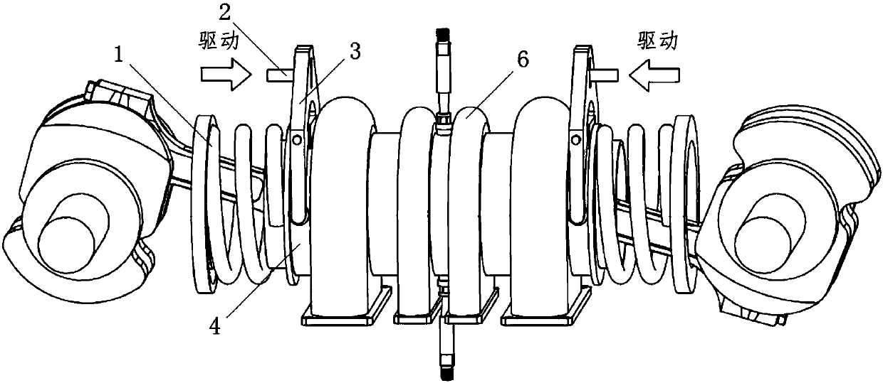
[0026] as attached figure 1 , 3 As shown in and 4, the present invention provides a variable valve timing mechanism based on sliding cylinder liners, which includes sliding cylinder liners 4, 5 on both sides, two electro-hydraulic drive devices 2, 8, rockers 3 on both sides , 7, and locking spring 1,9.

[0027] Air holes distributed along the circumferential direction are processed on the surfaces of the sliding cylinder sleeves 4 and 5;

[0028] Sliding cylinder liners 4,5 are sleeved on the inner side of fixed cylinder liner 6, pistons are sleeved on the inner side of sliding cylinder liners 4,5, and sliding cylinder liners 4,5 are compressed and positioned by locking springs 1,9. Rocking bar 3,7 middle part is fixed with the boss on the fixed cylinder liner 6, and one side of rocking bar 3,7 is connected with driving device 2,8, and one side is conne...


PUM


Abstract

The invention discloses a variable valve timing phase mechanism based on a sliding cylinder sleeve. Exhaust openings and air inlets of an air cylinder are formed in the middle and the two sides of theair cylinder on average, the phase mechanism is mounted on the air cylinder, the ventilation manner of middle exhaust and two-side air inlet of the air cylinder can be achieved, and two-stroke and four-stroke ventilation needs can be met at the same time; the air inlets and the exhaust openings of the air cylinder can also be formed in the middle and the two sides of the air cylinder on average,the phase mechanism is mounted on the air cylinder to achieve the ventilation manner of middle air inlet and two-side exhaust of the air cylinder, it can be ensured that the average indicating pressure and ventilating characteristics of an engine under all stations are more optimal, and the mechanism is suitable for optimizing the ventilation process, optimizing the combustion structure and improving the engine performance under the different rotating speeds

Description

technical field [0001] The invention relates to a variable valve phase mechanism of an internal combustion engine, in particular to a variable valve phase mechanism of an opposed-piston two-stroke engine, and belongs to the technical field of internal combustion engines. Background technique [0002] The opposed-piston two-stroke engine cancels the complicated valve train and cylinder head, its weight can be greatly reduced, and the power density and thermal efficiency can be effectively improved. As one of the technical approaches to deal with the energy crisis and environmental pollution challenges, it has attracted attention and research . However, the problem of emissions and particulate matter has always been a key issue restricting the application of opposed-piston two-stroke engines. One of the main reasons is that in opposed-piston two-stroke engines, the intake and exhaust ports arranged at both ends of the cylinder liner The air exchange process is completed, and ...

Claims


Application Information

Patent Timeline
Patent Type & Authority Applications(China)
IPC IPC(8): F01L5/06F01L9/00F02D13/02F01L9/10
CPCF01L5/06F01L9/00F02D13/0215F02D13/028Y02T10/12
Inventor 李向荣马赫阳杨伟
Owner BEIJING INSTITUTE OF TECHNOLOGYGY
Why Eureka
Try Eureka