Fiber displacement sensor demodulation method

A technology of displacement sensor and demodulation method, which is applied in the field of optical fiber displacement sensor demodulation, can solve the problems of great influence on sensor performance and poor environmental adaptability, and achieves the effect of overcoming environmental adaptability, simplifying structure and realizing precision

Active Publication Date: 2018-04-17
山东博艺节能科技有限公司
View PDF11 Cites 9 Cited by
  • Summary
  • Abstract
  • Description
  • Claims
  • Application Information

AI Technical Summary

Problems solved by technology

[0005] The technical problem to be solved by the present invention is to overcome the defect that the performance of the sensor is greatly affected by the change of factors such as poor environmental adaptability and jittering of the optical signal and environmental temperature during the working process of the existing demodulation device, and to provide a demodulation of the optical fiber displacement sensor device, thereby solving the above-mentioned problems

Method used


Image

  • Fiber displacement sensor demodulation method
  • Fiber displacement sensor demodulation method
  • Fiber displacement sensor demodulation method

Examples


Embodiment

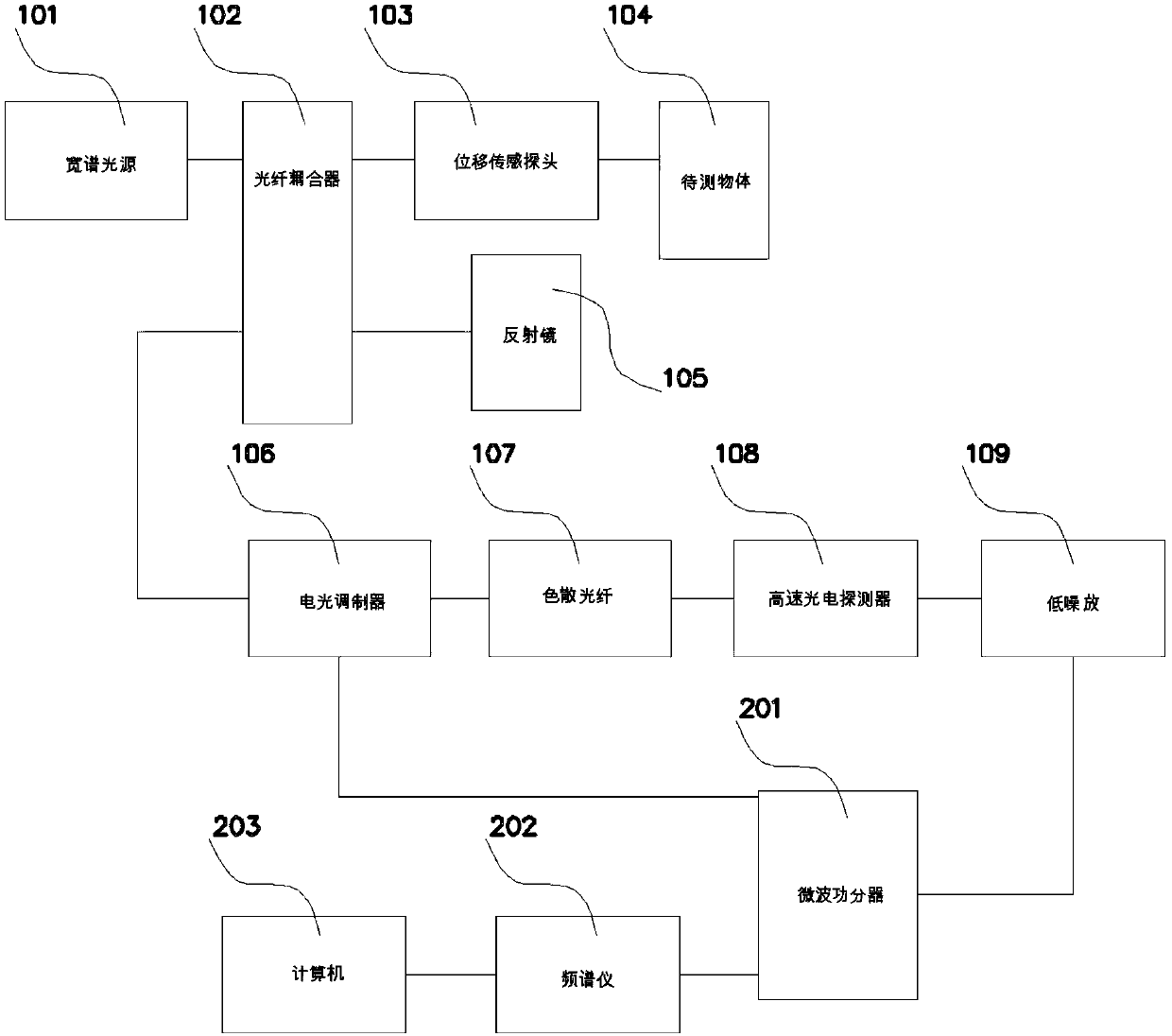
[0021] Example: such as Figure 1-2 As shown, the present invention provides a fiber optic displacement sensor demodulation device, including a wide-spectrum light source 101, an electro-optic modulator 106 and a computer 203, the output end of the wide-spectrum light source 101 is connected to the fiber coupler 102, and the connection of an output end of the fiber coupler 102 A displacement sensing probe 103, the displacement sensing probe 103 is connected to the object to be measured 104, and the surface of the optical coupler 102 is provided with a reflector 105, and the output port of the fiber coupler 102 and the reflector 105 constitute a Michelson interferometer, Michelson The output end of the interferometer is connected to the electro-optic modulator 106, and the modulated signal output by the electro-optic modulator 106 is incident on the high-speed photodetector 108 after passing through the dispersion fiber 107. Amplifier 109 amplifies, and the output end of low-no...


PUM


Abstract

The invention discloses a demodulation method based on a fiber displacement sensor demodulation device; the demodulation device comprises a wide spectrum light source, an electric light modulator anda computer; the output end of the wide spectrum light source is connected with a fiber coupler; one output end of the fiber coupler is connected with a displacement sensing probe; the displacement sensing probe is connected with a to-be-tested object; the surface of the fiber coupler is provided with a reflector; the output port of the fiber coupler and the reflector form a Michelson interferometer; a demodulation signal outputted by the electric light modulator passes a dispersion fiber and enters a high speed photoelectric detector; the high speed photoelectric detector converts the light signal into a microwave signal; the microwave signal is amplified by a low noise amplifier; the output end of the low noise amplifier is connected with a microwave power divider. The element parametersof the system can be set so as to freely adjust the resolution of the displacement sensing system; the nanometer level displacement sensing precision can be realized through parameter optimization, thus solving the problems that factors like a poor environment adaptability and a light signal jitter ambient temperature can greatly affect the sensor performance.

Description

technical field [0001] The invention relates to a demodulation method, in particular to a demodulation method of an optical fiber displacement sensor. Background technique [0002] The basic working principle of the optical fiber sensor is to send the optical signal from the light source to the modulator through the optical fiber, so that after the parameter to be measured interacts with the light entering the modulation area, the optical properties of the light (such as light intensity, wavelength, frequency, phase, etc.) , polarization state, etc.) changes and becomes the modulated signal source, which is sent to the optical detector through the optical fiber, and after demodulation, the measured parameters are obtained [0003] At present, optical fiber displacement sensors mainly include fiber grating, fiber optic F-P and fiber M-Z interferometer and other types of sensors. Among them, the power utilization rate of the fiber grating sensor is low, the measurement accurac...

Claims


Application Information

Patent Timeline
Patent Type & Authority Applications(China)
IPC IPC(8): G01B11/02
CPCG01B11/02
Inventor 卢平
Owner 山东博艺节能科技有限公司
Why Eureka
Try Eureka