Device for driving vehicle

An automobile driving device and automobile technology, which is applied in power plant, electric power plant, pneumatic power plant, etc., can solve the problems of inability to generate shaft torque, difficulty in ensuring MG installation space, and difficulty in realizing hybrid vehicles, etc. The effect of reducing probability, preventing short circuit, reducing shear resistance

Inactive Publication Date: 2018-04-17
DENSO CORP
View PDF9 Cites 1 Cited by
  • Summary
  • Abstract
  • Description
  • Claims
  • Application Information

AI Technical Summary

Problems solved by technology

However, in the technique of the above-mentioned Patent Document 1, since the output shaft of the MG is directly connected to the power transmission mechanism without a reduction mechanism, in the case of a small MG, the shaft required for EV running may not be produced. Torque (torque of the drive shaft), making it difficult to achieve EV driving, an important function of hybrid vehicles
In addition, in order to generate the shaft torque required for EV running, it is necessary to increase the size of the MG. In this case, it is difficult to secure the installation space for the MG.

Method used


Image

  • Device for driving vehicle
  • Device for driving vehicle
  • Device for driving vehicle

Examples


Embodiment 1

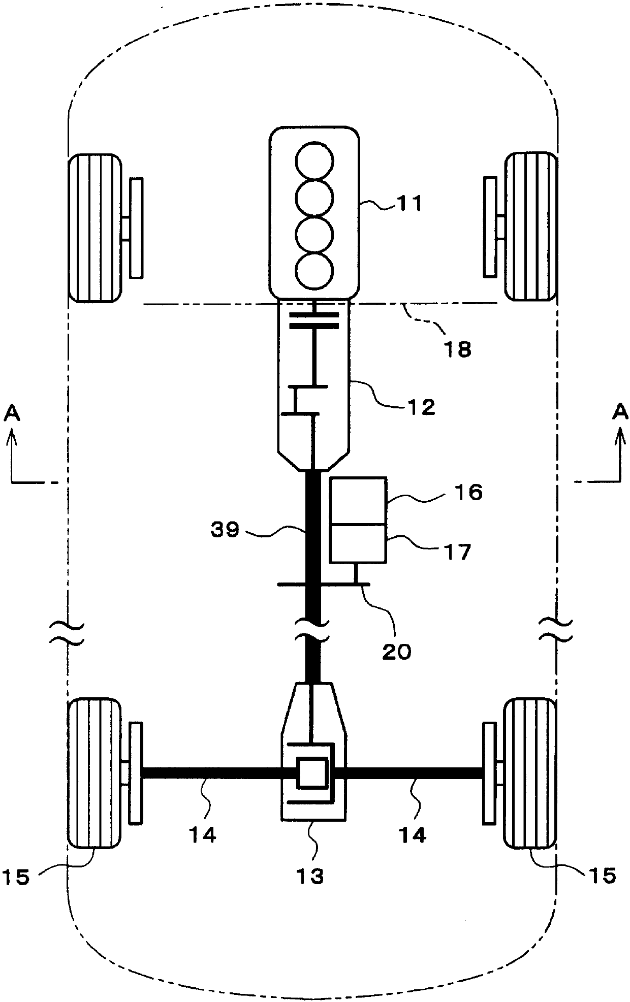
[0043] according to Figure 1 to Figure 5 , the first embodiment will be described. First, according to figure 1 with figure 2 , a schematic configuration of a drive system of a hybrid vehicle will be described.

[0044] Such as figure 1 As shown, an engine 11 serving as a power source of the automobile and a transmission 12 connected to the above-mentioned engine 11 are mounted on the front side of the automobile. The transmission 12 is a mechanical transmission, and may be a stepping transmission that switches gears step by step from a plurality of gears, or may be a CVT (continuously variable transmission) that changes gears continuously. The above-mentioned engine 11 and transmission 12 are arranged longitudinally so that the axial direction of the output shaft (crankshaft) of the engine 11 is the front-rear direction of the vehicle. The power of the output shaft of the engine 11 is transmitted to the transmission 12, and the power of the output shaft of the transmis...

Embodiment 2

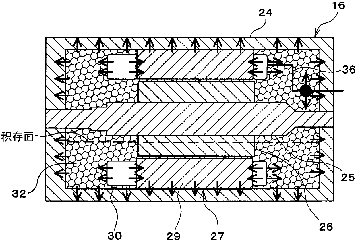
[0070] Next, use Image 6 Embodiment 2 will be described. However, the same symbols are attached to the parts substantially the same as those of the first embodiment described above, and descriptions thereof are omitted or simplified, and the parts different from the first embodiment described above will be mainly described.

[0071] Such as Image 6 As shown, in the second embodiment, in the case 24 of the MG 16 , on both sides in the axial direction of the stator core 29 , solid bodies 37 for heat dissipation are provided respectively. The aforementioned solid body 37 is arranged to be in contact with at least the coil end portion of the stator winding 30 (portion protruding from the axial end surface of the stator core 29 ) and the inner surface (inner peripheral surface and axial inner surface) of the case 24 . By this, if Image 6 As indicated by arrows in , the heat at the coil ends of the stator winding 30 of MG 16 can be transferred to case 24 via solid 37 to be dis...

Embodiment 3

[0075] Next, use Figure 7 Embodiment 3 will be described. However, the same symbols are attached to the parts substantially the same as those of the first embodiment described above, and descriptions thereof are omitted or simplified, and the parts different from the first embodiment described above will be mainly described. Such as Figure 7 As shown, in the third embodiment, between the output shaft of the speed reducer 17 and the power transmission mechanism 20, a clutch 38 for cutting off or connecting the power transmission is provided. The aforementioned clutch 38 may be a hydraulically driven plate clutch, may also be an electromagnetically driven electromagnetic clutch, or may be a mechanical claw clutch. The clutch 38 is provided separately from the speed reducer 17 (that is, it is provided outside the housing of the speed reducer 17). In addition, the clutch 38 may be provided integrally with the speed reducer 17 (that is, the clutch 38 may be provided in the hou...


PUM


Abstract

A device for driving a vehicle is provided with an engine (11) serving as a power source for the vehicle and a transmission (12) connected to the engine (11). The engine (11) and the transmission (12)are longitudinally disposed so that the axial direction of the output shaft of the engine (11) is oriented in the longitudinal direction of the vehicle. The driving device is provided with a motor generator (MG) (16) serving as a power source for the vehicle and a decelerator (17) connected to the MG (16). The MG (16) and the decelerator (17) are disposed on the outside of an engine compartment in which the engine (11) is accommodated. The output shaft of the decelerator (17) is linked, so as to enable transmission of power, to a powertrain for transmitting the power from the output shaft ofthe transmission (12) to driveshafts (14) for wheels (15).

Description

[0001] References to related applications [0002] This application is based on Japanese Patent Application No. 2015-156831 filed on August 7, 2015 and Japanese Patent Application No. 2016-21262 filed on February 5, 2016, and the contents of the description are cited here. technical field [0003] The present invention relates to an automobile driving device including an engine and a motor generator as a power source of the automobile. Background technique [0004] In recent years, a hybrid vehicle equipped with an engine and a motor generator (hereinafter referred to as "MG") as a power source of an automobile has attracted attention in response to social demands for low fuel consumption and low exhaust emissions. Among the hybrid vehicles described above, for example, there is an automobile described in Patent Document 1 (Japanese Patent No. 3350314). In the vehicle described above, the transmission is connected to the engine via a clutch, the drive shaft of the wheels is...

Claims


Application Information

Patent Timeline
Patent Type & Authority Applications(China)
IPC IPC(8): B60K6/40B60K11/02B60L9/18B60L11/14B62D25/20H02K9/19B60K1/04B60K6/24B60K6/26B60K6/36B60K6/405B60K6/485B60K6/54B60L50/16
CPCB60K6/40B60K6/48H02K3/24H02K7/116H02K9/197B60K1/00B60K17/16B60L2240/48B60L50/16B62D25/20H02K3/345H02K7/006H02K9/19B60K2006/4808B60K2006/4833H02K3/12B60K1/04Y02T10/62Y02T10/64Y02T10/7072Y02T10/72Y02T10/70B60K6/24B60K6/26B60K6/36B60K6/547B60K11/02B62D25/2009
Inventor 真贝知志佐藤卓中冈卓郎前川武雄近藤啓次
Owner DENSO CORP
Why Eureka
Try Eureka