Supercharge Your Innovation With Domain-Expert AI Agents!

Long-sized polarizing plate with optical compensation layer and organic el panel using the same

An optical compensation layer, strip-shaped technology, applied in the direction of optics, optical elements, polarizing elements, etc., can solve the problems of difficulty in controlling the slow axis, deviation of the optical axis from the set direction, and uneven characteristics in the width direction, achieving Excellent reflective hue and viewing angle characteristics

Active Publication Date: 2018-04-17
NITTO DENKO CORP
View PDF12 Cites 0 Cited by
  • Summary
  • Abstract
  • Description
  • Claims
  • Application Information

AI Technical Summary

Problems solved by technology

However, many problems remain in the manufacture of circular polarizing plates using roll-to-roll: the optical axis of the optical film is shifted from the set direction due to bonding, and the elongated retardation film (such as λ / 4 Difficulty in controlling the slow axis in the inclination direction of the plate), uneven characteristics in the width direction, etc.

Method used


Image

  • Long-sized polarizing plate with optical compensation layer and organic el panel using the same
  • Long-sized polarizing plate with optical compensation layer and organic el panel using the same

Examples


Embodiment 1

[0106] (Production of polycarbonate resin film)

[0107] Polymerization was performed using a batch polymerization apparatus including two vertical reactors equipped with stirring blades and a reflux cooler controlled at 100°C. 9,9-[4-(2-hydroxyethoxy)phenyl]fluorene (BHEPF), isosorbide (ISB), diethylene glycol (DEG), diphenyl carbonate (DPC) and magnesium acetate The hydrate becomes BHEPF / ISB / DEG / DPC / magnesium acetate=0.348 / 0.490 / 0.162 / 1.005 / 1.00×10 according to the molar ratio -5 way of investing. After the inside of the reactor was sufficiently replaced with nitrogen (oxygen concentration: 0.0005 to 0.001% by volume), it was heated with a heat medium, and stirring was started when the internal temperature reached 100°C. 40 minutes after the start of the temperature rise, the internal temperature was controlled to be 220° C. to maintain the temperature, and at the same time the pressure was reduced, and it was set to 13.3 kPa over 90 minutes after reaching 220° C. Introdu...

Embodiment 2~5 and comparative example 1~3

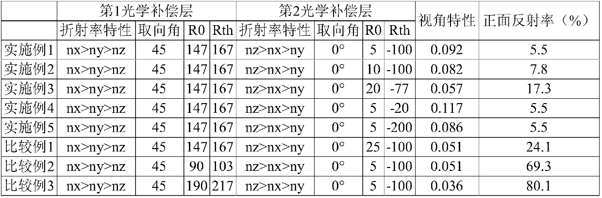
[0133] A polarizing plate with an optical compensation layer and an organic EL panel were produced with the configuration shown in Table 1. The obtained polarizing plate and organic EL panel with an optical compensation layer were subjected to the same evaluation as in Example 1. As shown in Table 1, the organic EL panels of Examples 2 to 5 had good viewing angle characteristics and front reflectance. Furthermore, regarding these organic EL panels, it was confirmed that a neutral reflection hue was realized in any of the frontal direction and the oblique direction. On the other hand, the organic EL panels of Comparative Examples 1 to 3 had insufficient front reflectance and insufficient antireflection characteristics.


PUM

PropertyMeasurementUnit
Reduced viscosityaaaaaaaaaa
Glass transition temperatureaaaaaaaaaa
Thicknessaaaaaaaaaa

Abstract

To realize excellent reflective hue and visual field angle characteristics and to provide a polarizing plate with an optical compensation layer that can be obtained with excellent manufacturing efficiency. A polarizing plate 100 with an optical compensation layer being long-sized and used for an organic EL panel includes a long-sized polarizer 10, a long-sized first optical compensation layer 30,and a long-sized second optical compensation layer 40, in this order. An absorption axis direction of the polarizer 10 is substantially orthogonal or parallel to a longer direction. The first opticalcompensation layer 30 exhibits a refractive index characteristic of nx>ny>=nz, with Re(550) of 100 to 180 nm and an Nz coefficient of 1.0 to 2.0 and satisfies Re(450)<Re(550). A slow axis direction ofthe first optical compensation layer and the longer direction form an angle of 35-degree to 55-degree. The second optical compensation layer exhibits a refractive index characteristic of nz>nx>ny, with Re(550) of 5 to 20nm and Rth(550) of -200 to -20 nm. A slow axis direction of the second optical compensation layer is substantially orthogonal or parallel to the longer direction.

Description

technical field [0001] The present invention relates to a long polarizing plate with an optical compensation layer and an organic EL panel using the same. Background technique [0002] In recent years, with the spread of thin displays, displays (organic EL display devices) equipped with organic EL panels have been proposed. Since the organic EL panel has a highly reflective metal layer, problems such as reflection of external light and reflection of the background are prone to occur. Therefore, there is known a method of preventing these problems by disposing a circular polarizing plate on the viewing side. As a general circular polarizing plate, there is known a circular polarizing film obtained by laminating a retardation film (typically a λ / 4 plate) so that its slow axis forms an angle of about 45° with respect to the absorption axis of the polarizer. piece. In addition, in order to further improve antireflection characteristics, it has been attempted to laminate vario...

Claims


Application Information

Patent Timeline
IPC IPC(8): G02B5/30B32B7/02H01L51/50H05B33/02B32B7/023
CPCG02B5/30H05B33/02B32B7/023G02B5/305H10K59/8791G02B5/3083B32B2307/42
Inventor 饭田敏行
Owner NITTO DENKO CORP
Features
  • R&D
  • Intellectual Property
  • Life Sciences
  • Materials
  • Tech Scout
  • Unparalleled Data Quality
  • Higher Quality Content
  • 60% Fewer Hallucinations
Learn More