Anti-reflection film and production method therefor

An anti-reflection film and refractive index technology, applied in sputtering plating, ion implantation plating, coating, etc., can solve the problems of easy coloring of reflection hue, reduce visual reflectivity, etc., and achieve excellent mechanical properties and excellent reflection Characteristics, the effect of excellent reflection hue

Active Publication Date: 2015-09-30
NITTO DENKO CORP
View PDF4 Cites 4 Cited by
  • Summary
  • Abstract
  • Description
  • Claims
  • Application Information

AI Technical Summary

Problems solved by technology

However, if the visual reflectance is to be reduced, there is a problem that the reflective hue is easy to produce coloring

Method used


Image

  • Anti-reflection film and production method therefor
  • Anti-reflection film and production method therefor
  • Anti-reflection film and production method therefor

Examples


Embodiment 1

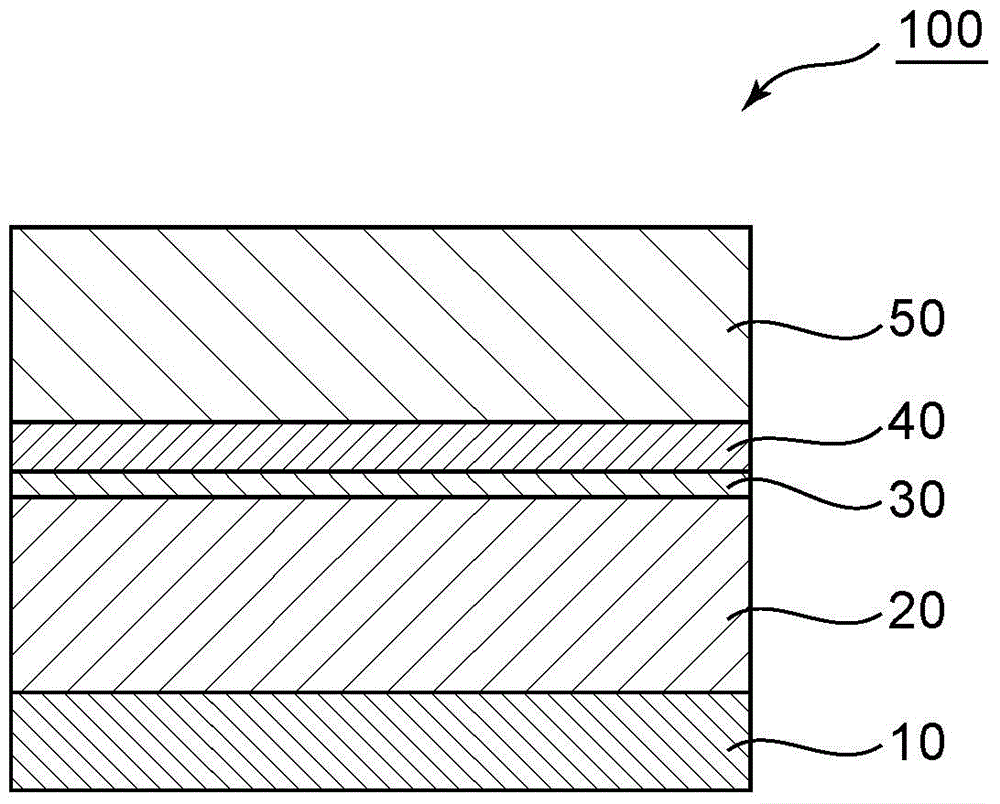
[0092] A triacetyl cellulose (TAC) film with a hard coat layer (refractive index: 1.53) was used as a substrate. On the other hand, the following coating solution (composition for forming a medium refractive index layer) was prepared: zirconia particles (average particle diameter: 40 nm, a resin composition with a refractive index of 2.19) (manufactured by JSR Corporation, trade name "Opstar KZ series") was diluted to 3%. This coating solution was coated on the above-mentioned substrate using a bar coater, dried at 60°C for 1 minute, and then irradiated with ultraviolet rays with a cumulative light intensity of 300mJ to form a middle refractive index layer (refractive index: 1.68, thickness: 100nm ). Next, by sputtering Nb 2o 5 , thereby forming a high-refractive-index layer (refractive index: 2.33, thickness: 12 nm) on the medium-refractive-index layer. Furthermore, by sputtering SiO 2 , thereby forming a low-refractive-index layer (refractive index: 1.47, thickness: 110...

Embodiment 2~5 and comparative example 1~4

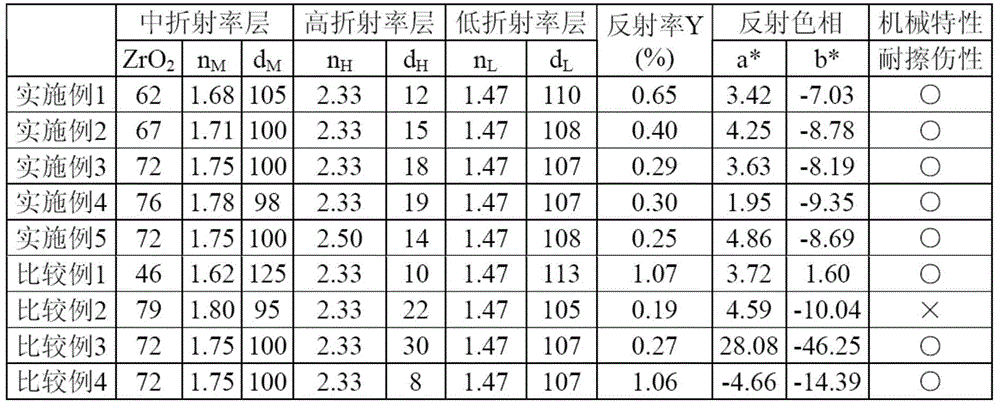
[0094] An antireflection film was prepared with the configuration shown in Table 1. The obtained antireflection film was subjected to the evaluations of (1) and (2) above. The results are shown in Table 1.

[0095] In addition, in each Example and a comparative example, the same base material was used. The refractive index of the middle refractive index layer was changed by changing the content of zirconia particles in the coating liquid as shown in Table 1. The refractive index of the high-index layer was obtained by sputtering TiO 2 (refractive index: 2.50) instead of Nb 2 o 5 And change. SiO is used for the refractive index of the low refractive index layer 2 and become constant. In addition, the thickness of the middle refractive index layer is changed by changing the coating thickness of the coating liquid. The thicknesses of other layers were changed by changing the sputtering thickness.

[0096] [Table 1]

[0097]

[0098] *ZrO 2 It is the content in all s...

Embodiment 6~7 and comparative example 5~7

[0100] An antireflection film was prepared with the configuration shown in Table 2. The obtained antireflection film was subjected to the evaluations of (1) and (2) above. The results are shown in Table 2.

[0101] In addition, in each Example and a comparative example, the same base material was used. The medium refractive index layer is formed using a resin composition containing titanium oxide particles (manufactured by Toyo Ink Co., Ltd., trade name "LIODURAS TYT series"), and the refractive index of the medium refractive index layer is determined by making the titanium oxide particles in the coating liquid content varies. The refractive index of the high refractive index layer uses Nb 2 o 5 and become constant. SiO is used for the refractive index of the low refractive index layer 2 and become constant. In addition, the thickness of the middle refractive index layer is changed by changing the coating thickness of the coating liquid. The thicknesses of other layers...


PUM

PropertyMeasurementUnit
thicknessaaaaaaaaaa
thicknessaaaaaaaaaa
thicknessaaaaaaaaaa

Abstract

Provided is an anti-reflection film that can be produced in a highly-productive manner and at low cost, that has excellent reflection properties (i.e., low reflectivity) over a wide spectrum and excellent reflection hues that are close to neutral, and that has excellent mechanical properties. This anti-reflection film comprises a substrate, and, in order from the substrate side, a medium refractive index layer, a high refractive index layer, and a low refractive index layer. The refractive index of the substrate ranges from 1.45 to 1.65. The medium refractive index layer: is formed by applying and curing a composition for forming a medium refractive index layer, which contains a binder resin and inorganic particles, on the substrate; has a refractive index ranging from 1.67 to 1.78; and has a thickness of 70 nm to 120 nm. The high refractive index layer has a refractive index that ranges from 2.00 to 2.60, and has a thickness of 10 nm to 25 nm. The low refractive index layer has a refractive index that ranges from 1.35 to 1.55, and has a thickness of 70 nm to 120 nm.

Description

technical field [0001] The invention relates to an anti-reflection film and a manufacturing method thereof. More specifically, the present invention relates to a method for manufacturing an anti-reflection film including a dry process and a wet process, and the anti-reflection film obtained by the method. Background technique [0002] Conventionally, in order to prevent outside light from being reflected on the display screens of CRT (Cathode-Ray Tube, cathode ray tube), liquid crystal display devices, plasma display panels, etc., anti-reflection films arranged on the surface of display screens have been widely used. As an antireflection film, for example, a multilayer film having a layer made of a material with a medium refractive index, a layer made of a material with a high refractive index, and a layer made of a material with a low refractive index is known. It is known that high antireflection performance (low reflectance in a wide band) can be obtained by using the ab...

Claims


Application Information

Patent Timeline
Patent Type & Authority Applications(China)
IPC IPC(8): G02B1/11B32B7/02G02B5/30G02F1/1335G09F9/00
CPCG02B5/30B32B7/02G02B1/11G02B1/113C23C14/34G02B5/3033
Inventor 岸敦史上野友德仓本浩贵
Owner NITTO DENKO CORP
Why Eureka
Try Eureka