Cold forging extrusion concave die

A die and cold forging technology, applied in forging/pressing/hammer devices, forging/pressing/hammering machinery, transportation and packaging, etc. problems, to achieve the effect of reducing the difficulty of cutting, high mechanical properties of the product, and improving the utilization rate of materials

Inactive Publication Date: 2018-04-20
江苏威鹰机械有限公司
View PDF12 Cites 1 Cited by
  • Summary
  • Abstract
  • Description
  • Claims
  • Application Information

AI Technical Summary

Problems solved by technology

The existing manufacturing process is to select the bar and directly use the cutting process to produce it. The disadvantage of this process is that the production efficiency of cutting is low, and it is only suitable for single piece or small batch production; the other is hot forging and then cutting to form the inner wall. For gears, the two production processes adopt the traditional cutting method to form gears, which are suitable for small batch production, with large capital investment in equipment, low production efficiency, low material utilization rate, long production cycle and high processing cost; secondly, the cutting process The middle metal flow line is cut off, the tooth surface is not compact, and the mechanical properties are poor, which makes it difficult to meet the quality requirements of auto parts.
In short, the existing manufacturing process: 1. Large investment in machine tool equipment; 2. Large tool loss; 3. Especially due to the small size of the primary transmission gear, the cutting of the helical tooth surface is difficult and the production efficiency is low; 4. The cost is high; 5. The base material is directly processed, the metal flow line is cut off, the tooth strength is low, and the quality is poor; 6. Waste metal materials

Method used


Image

  • Cold forging extrusion concave die
  • Cold forging extrusion concave die
  • Cold forging extrusion concave die

Examples


Embodiment

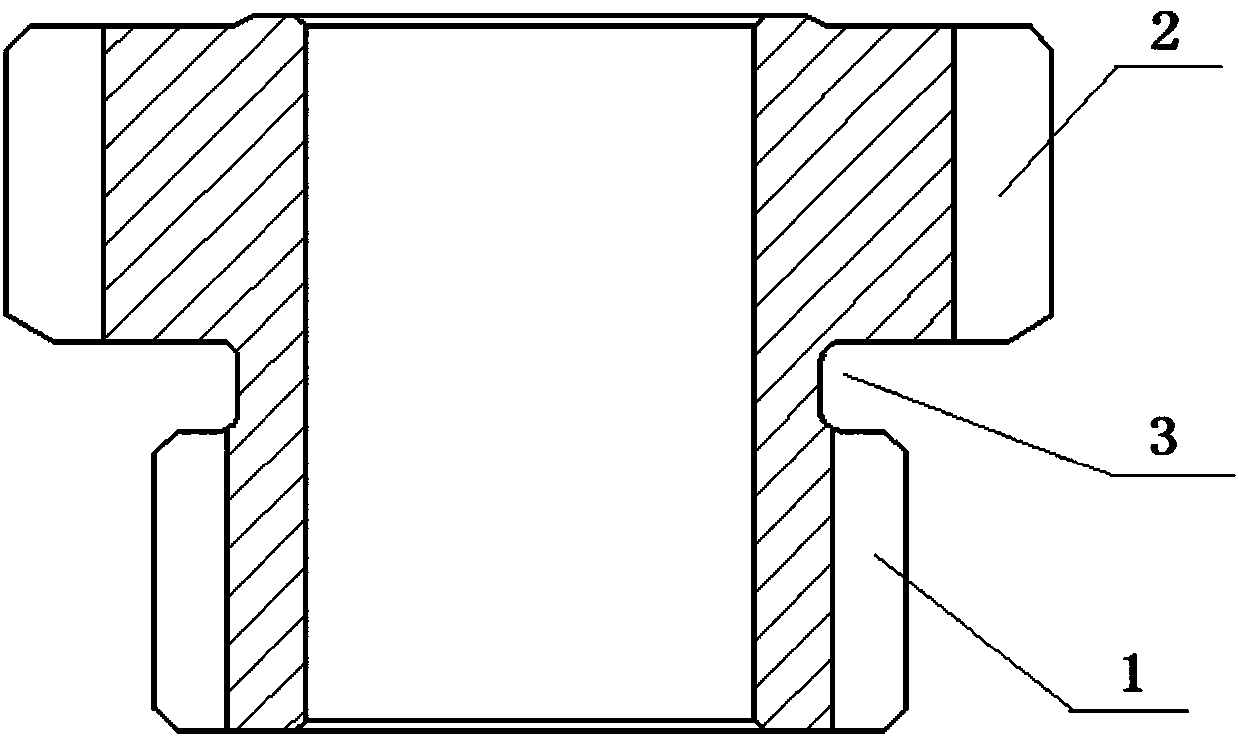
[0016] Example: see figure 1 As shown, a sun gear of an automobile automatic transmission includes a hollow shaft body, the outer surface of the hollow shaft body is provided with a primary transmission gear 1 and a secondary transmission gear 2, and the primary transmission gear 1 and secondary transmission gear 2 An annular groove 3 is arranged between them, and the first-stage transmission gear 1 and the second-stage transmission gear 2 are helical gears.

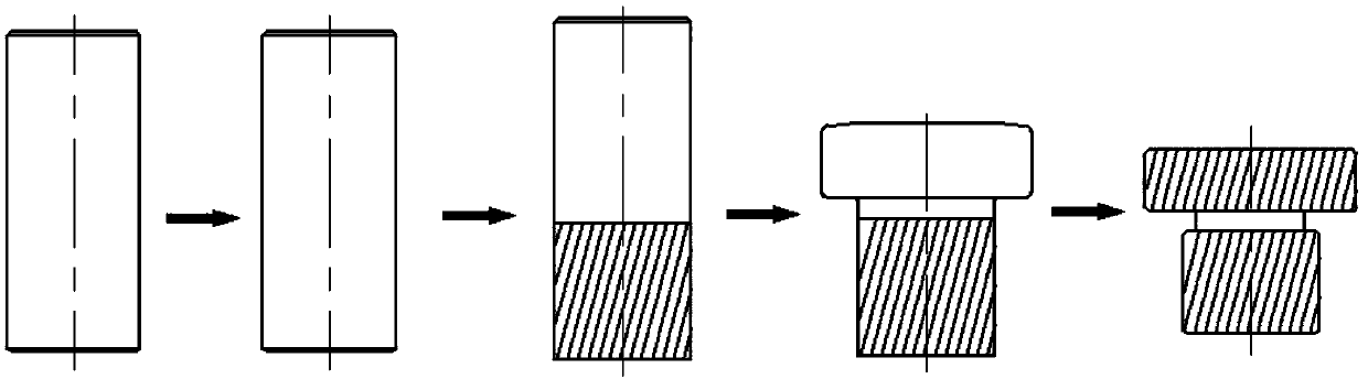
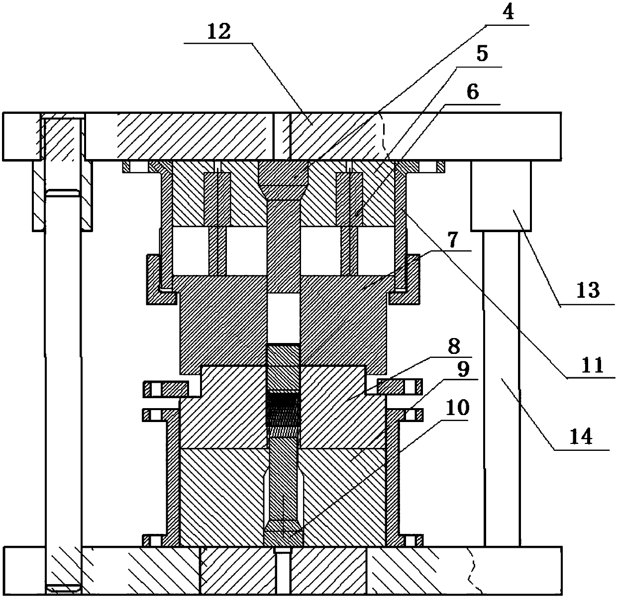
[0017] see figure 2 and image 3 As shown, the manufacturing process of the automotive automatic transmission sun gear includes the following steps: ①Blanking: Select the diameter of the bar, and cut the required length of the bar according to the size of the drawing; ②Spheroidizing annealing: Put the bar into the furnace and heat it to 720°C Spheroidizing annealing at -780°C, spheroidizing rate ≥ 90%, hardness ≤ 80HRC; ③ Billet making: peeling to remove scale and chamfering; ④ Shot blasting: Send the billet after mak...


PUM


Abstract

The invention discloses a cold forging extrusion concave die. An upper die positioning sleeve is arranged in a fixed guiding ring and moves vertically along the inner wall of the fixed guiding ring under the action of the external force. A nitrogen spring is arranged between the upper die positioning sleeve and a movable upper concave die. The movable upper concave die and a lower concave die aretwo coaxially-engaged axial through hole round sleeves. The movable upper concave die is connected with the fixed guiding ring. The fixed guiding ring is fixed on an upper die frame. The upper die frame is connected with a die frame guiding sleeve. The die frame guiding sleeve is arranged on a guiding column in a sleeving mode and can move vertically along the guiding column under the action of the external force. A bearing block is located at the bottom of the lower concave die. A material ejecting rod perpendicularly penetrates through the bearing block and enters a die cavity of the lower concave die. By means of the cold forging extrusion concave die, a sun wheel is formed, the cutting machining difficulty of a sun wheel of small size is reduced, the production efficiency is high, thematerial utilization rate is high, the processing cost is low, and the tooth surface strength of a first-level transmission gear is improved.

Description

technical field [0001] The invention relates to a sun gear of an automatic transmission of an automobile, in particular to an extrusion die for manufacturing a sun gear of a small-sized automatic transmission of an automobile. Background technique [0002] The sun gear is an important part of the car automatic transmission for shifting gears and transmitting variable loads. It generally includes a hollow shaft body. The outer surface of the hollow shaft body is provided with a primary transmission gear 1 and a secondary transmission gear 2. The primary An annular groove 3 is provided between the transmission gear 1 and the secondary transmission gear 2, and the primary transmission gear 1 and the secondary transmission gear 2 are helical gears. Due to the small size of the sun gear, it is more difficult to cut the helical tooth surface. The diameter of the dedendum circle of some primary transmission gears is only 20mm. The existing manufacturing process is to select the ba...

Claims


Application Information

Patent Timeline
Patent Type & Authority Applications(China)
IPC IPC(8): B21J13/02B21K1/30
CPCB21J13/02B21K1/30
Inventor 张太良万永福张华文
Owner 江苏威鹰机械有限公司
Why Eureka
Try Eureka