
Stationary shoulder friction stir welding device and method for variable-angle fillet joints

A static shoulder and fillet joint technology, applied in the field of friction stir welding, can solve the problems of difficulty in obtaining defect-free welded joints, uneven temperature along the plate thickness, overheating of the weld surface, etc., to achieve repeated use and easy installation Sealing stack rings and post-weld cleaning, performance-enhancing effects

Active Publication Date: 2018-04-20
NANJING UNIV OF SCI & TECH
View PDF8 Cites 28 Cited by
  • Summary
  • Abstract
  • Description
  • Claims
  • Application Information

AI Technical Summary

Problems solved by technology

However, most of the industrial applications of FSW technology are mainly limited to simple butt joints. When applied to T-joints, fillet welds and box structures that are widely used in the manufacture of aircraft fuselages, ship decks, automobiles and train bodies, etc. , limited by the shoulder of the stirring tool, FSW technology is difficult to apply to the manufacture of these structures; when applying FSW technology to welding low thermal conductivity materials such as titanium alloys, due to the frictional heating between the shoulder of the stirring tool and the surface to be welded (produced 70% ~ 80% most of the heat), which makes the surface of the weld overheated and the temperature along the thickness of the plate is obviously uneven, which makes it difficult to obtain a defect-free welded joint

Method used


Image

  • Stationary shoulder friction stir welding device and method for variable-angle fillet joints
  • Stationary shoulder friction stir welding device and method for variable-angle fillet joints
  • Stationary shoulder friction stir welding device and method for variable-angle fillet joints

Examples


Embodiment

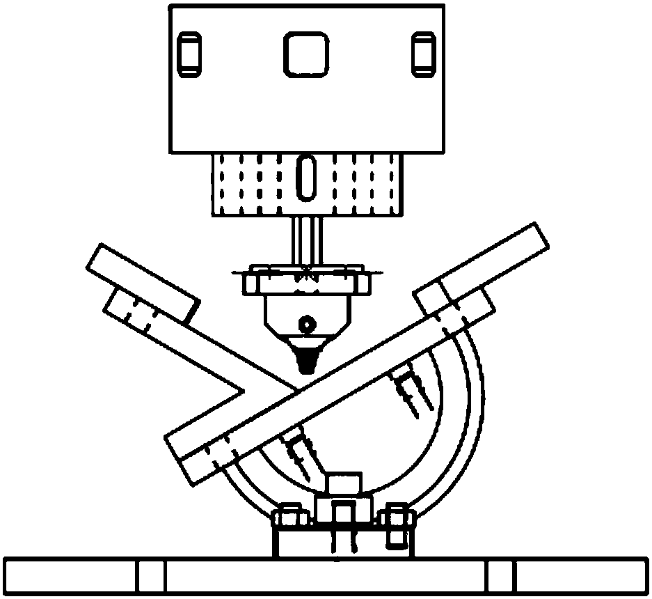
[0054] Based on the above device, a static shoulder friction stir welding method for fillet joints is provided.

[0055] In the welding example, the thickness of the aluminum alloy plate is 17mm, and the angle joint is 120°. The static shoulder stirring head is designed as follows: the static shoulder transition fillet radius is 8mm, the root diameter of the stirring needle is 16mm, the length is 16mm, the cone angle is 30°, and the root is strengthened. The shoulder diameter is 22mm and the length is 6mm.

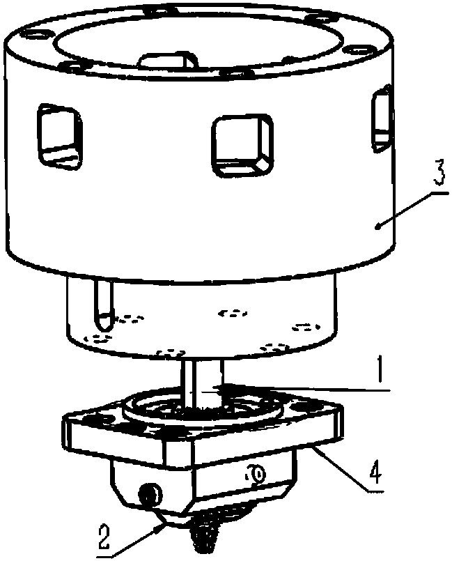
[0056] Step 1, use set screws to assemble and fix the stirring needle 1 on the knife handle of the machine head, then assemble and fix the first rigid connection device 3 and the second rigid connection device 4 in sequence, and then install the sealing stack ring 5 into the static The installation groove 22 of the shaft shoulder 2, then put the stationary shaft shoulder 2 into the rigid connection device 4, tighten the set screw, and press into the round holes 19, 20 on t...


PUM

PropertyMeasurementUnit
thicknessaaaaaaaaaa
thicknessaaaaaaaaaa

Abstract

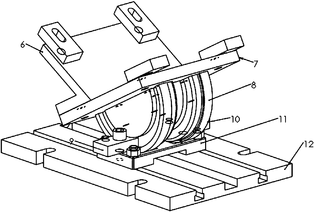
The invention provides a stationary shoulder friction stir welding device for variable-angle fillet joints. The stationary shoulder friction stir welding device comprises a stationary shoulder stirring head and a matched platform capable of changing the fillet weld angle and fixing a to-be-welded workpiece. The stationary shoulder stirring head comprises a stirring pin, a stationary shoulder, a rigid connecting device and a sealing stacking ring, wherein the stationary shoulder is connected with a spindle of a friction stir welding machine through rigid fixation, and the stainless steel sealing stacking ring is arranged between the stirring pin and the stationary shoulder and used for preventing aluminum alloy from being squeezed into a gap between the stationary shoulder and the stirringpin in the welding process. The platform capable of fixing the to-be-welded workpiece comprises a base plate for supporting an aluminum alloy plate, a semicircular sliding block capable of changing the inclination angle, pressing plates for fixing the sliding block, a base for supporting the sliding block, and a workbench with T-shaped grooves. According to fillet welds with different thicknessesand different angles, welding can be carried out only by adjusting the angles of the stationary shoulder and the base plate, and thus the time and cost for replacing the platform capable of fixing theto-be-welded workpiece when fillet welds with different angles are welded are avoided.

Description

technical field [0001] The invention relates to a friction stir welding method and device, in particular to a static shoulder friction stir welding method and device for variable angle fillet welds. Background technique [0002] Friction Stir Welding (FSW for short) is a solid phase joining technology invented by the British Welding Institute in 1991 (US5460317), especially suitable for welding low melting point alloys such as aluminum. Friction stir welding utilizes the friction heat generated by the shaft shoulder and the friction between the stirring needle and the workpiece to make the material near the welded joint reach a plastic state, and the material fluidity increases. When the stirring head moves forward, the plasticized material is squeezed by the shaft shoulder and Under the stirring action of the stirring needle, it is moved to the rear of the stirring head, and cooled to form a welded joint. The material is not melted during the welding process, and the maximu...

Claims


Application Information

Patent Timeline
Patent Type & Authority Applications(China)
IPC IPC(8): B23K20/12
CPCB23K20/1245
Inventor 周琦周雨奇王闻中其他发明人请求不公开姓名
Owner NANJING UNIV OF SCI & TECH
Learn More