
CCD and CAM optical contour grinder

An optical curve grinding and fuselage technology, applied in the field of CCD, can solve the problems of inability to achieve intelligent and automatic requirements, no CCD mirror pairing group, large workload of staff, etc., to achieve convenient programming and processing, and ensure effective cutting length. , the effect of reducing labor

Pending Publication Date: 2018-04-20
东莞市骏昂精密设备有限公司
View PDF11 Cites 0 Cited by
  • Summary
  • Abstract
  • Description
  • Claims
  • Application Information

AI Technical Summary

Problems solved by technology

[0004] The present invention provides a CCD, CAM optical curve grinding machine, which can effectively solve the problem that the grinding wheel at one end of the electric spindle in the prior art requires people to compare the processing graphics at all times during the grinding process of the workpiece in the background technology mentioned above. Inspection while processing, visual compensation work, the workload of the staff is heavy, there is no CCD mirror group, the parts cannot be imaged at a fixed magnification through the CCD mirror group, it is inconvenient for the staff to view, and it cannot realize intelligence and automation asked questions

Method used


Image

  • CCD and CAM optical contour grinder
  • CCD and CAM optical contour grinder

Examples


Embodiment

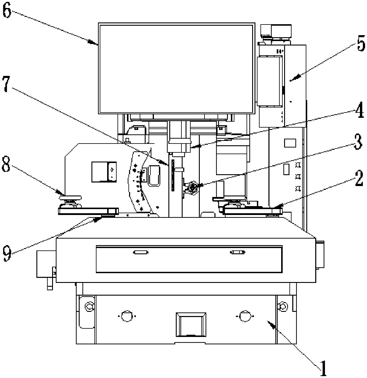
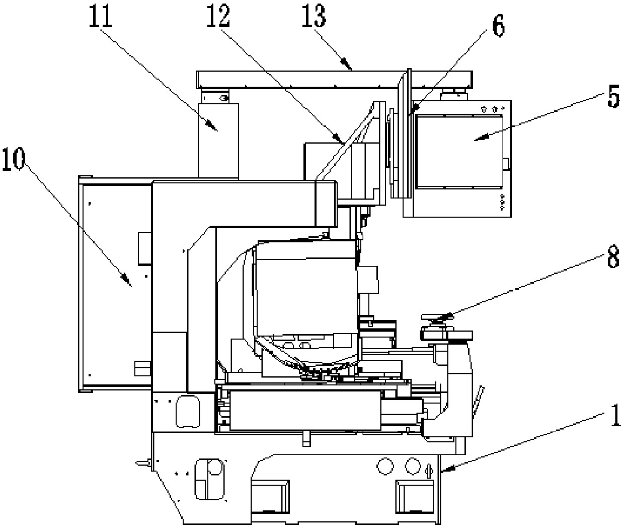
[0017] Example: such as Figure 1-2 As shown, the present invention provides a technical solution, a CCD, CAM optical curve grinder, including a lower body 1, a ZV working lifting platform 2, an electric spindle 3, a CCD mirror pair group 4, a control panel 5, a display screen 6, Mechanical reciprocating cutting device 7, hand wheel 8, three pendulum angle device 9, upper body 10, support rod 11, support 12 and rotating rod 13, upper end of lower body 1 is provided with upper body 10, and lower body 1 The upper end is provided with a ZV working lifting platform 2 near the front side of the upper fuselage 10, and a bracket 12 is arranged at the upper end of the upper fuselage 10 near the ZV working lifting platform 2, and the upper end of the upper fuselage 10 is provided with a support Rod 11, an electric spindle 3 is arranged on the front side of the upper body 10 near the lower part of the bracket 12, a display screen 6 is arranged on one end of the bracket 12, and a rotatin...


PUM


Abstract

The invention discloses a CCD and CAM optical contour grinder which comprises a lower machine body, an electric spindle, a CCD lens pair and a mechanical reciprocating cutting device. An upper machinebody is arranged at the upper end of the lower machine body. A ZV work lifting table is arranged at the position, close to the front side of the upper machine body, of the upper end of the lower machine body. A support is arranged at the position, close to the upper end of the ZV work lifting table, of the front side of the upper machine body. The electric spindle is arranged at the position, close to the lower portion of the support, of the front side of the upper machine body. The CCD and CAM optical contour grinder is scientific and reasonable in structure and safe and convenient to use; the CCD visual lens pair is arranged, the magnifying machining effect of a workpiece and a picture is displayed on a display screen, and program machining is facilitated through rough machining and finish machining; system automatic operation compensation is achieved, and use of labor force is reduced; and by means of the design, a dual-crank three-connecting-rod sliding block mechanism is adoptedby the mechanical reciprocating cutting device, the accurate cutting stroke and cutting stroke segment can be adjusted, the cutting effective length of parts can be guaranteed, and the functions of facilitating CCD lens focusing and the like can be achieved.

Description

technical field [0001] The invention relates to the technical field of optical curve grinders, in particular to a CCD, CAM optical curve grinder. Background technique [0002] CAD, CAM curve grinding machine is to install the CCD visual lens inspection system and automatic compensation system on the optical curve grinding machine. The machine tool adopts four-axis full-closed loop, full-time feedback, full-time adjustment, no need to describe the film multiplication image, and the processing process is very intuitive. Accurately understand the processing situation, detect feedback while processing, and automatically compensate according to the algorithm of the system to achieve the ideal effect. [0003] However, the CCD and CAM optical curve grinding machines currently on the market are not only complex in structure, but also have a single function. In the process of grinding the workpiece, the grinding wheel at one end of the electric spindle in the prior art needs people ...

Claims


Application Information

Patent Timeline
Patent Type & Authority Applications(China)
IPC IPC(8): B24B19/00B24B47/20B24B49/12B24B51/00
CPCB24B19/00B24B47/20B24B49/12B24B51/00
Inventor 唐东升
Owner 东莞市骏昂精密设备有限公司
Learn More