Heat storage combustion device with annular rotating valve

A regenerative combustion and rotary valve technology, applied in valve device, combustion method, combustion type and other directions, can solve the problems of unreasonable structural design, high leakage value, affecting the efficiency of waste gas treatment, etc., to achieve simple and stable structure and increase sealing effect. , the effect of preventing leakage

Active Publication Date: 2018-04-20
JIANGSU ZHONGYAN ECOPURE TECH CO LTD
View PDF3 Cites 5 Cited by
  • Summary
  • Abstract
  • Description
  • Claims
  • Application Information

AI Technical Summary

Problems solved by technology

However, due to the unreasonable structural design of the current rotary valve, there is still a defect that the leakage value is too high, which directly affects the efficiency of exhau...

Method used


Image

  • Heat storage combustion device with annular rotating valve
  • Heat storage combustion device with annular rotating valve
  • Heat storage combustion device with annular rotating valve

Examples


no. 1 example

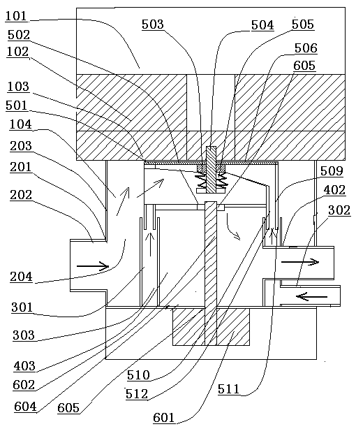
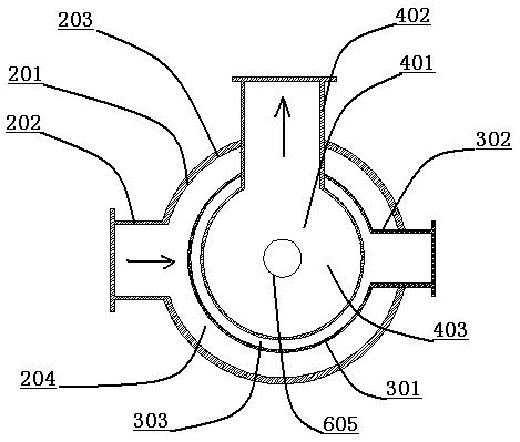
[0028] Such as figure 1 As shown, the regenerative combustion device with an annular rotary valve includes: a combustion chamber 101 , a regenerator 102 , an annular gas distribution plate 103 and an annular rotary valve 104 . The annular rotary valve 104 includes: an annular intake box 201 , an exhaust box 401 , an annular scavenging box 301 , a rotary valve core 501 and a transmission device 601 . Such as figure 2 As shown, an air intake pipe 202 is installed on the shell 203 of the annular air intake box 201 , and the air intake pipe 202 communicates with the annular air intake passage 204 inside the shell 203 . The annular scavenging air box 301 is installed inside the annular air intake box 201 , the air scavenging pipe 302 of the annular air scavenging box 301 passes through the annular air intake box 201 , and communicates with the annular air scavenging channel 303 of the annular air scavenging box 301 . The exhaust box 401 is installed inside the annular scavenging...

no. 2 example

[0031] Such as Figure 5 As shown, an annular air guide plate 801 is installed in the annular scavenging air box 301, such as Figure 6 As shown, the retaining ring 802 of the annular air guiding plate 801 is provided with several air guiding holes 803, and the air guiding holes 803 are connected with an air guiding tube 804 installed thereon. Such as Figure 5 As shown, the retaining ring 802 of the annular air guide plate 801 is installed in the middle of the annular scavenging air box 301 , and the purge cleaning gas in the annular air scavenging box 301 is discharged through the air guide hole 803 and the air guide pipe 804 . Such as Figure 5As shown, one or more annular porous seals 805 are installed on the annular air guide plate 801 . like Figure 7 As shown, the through hole 806 of the annular porous seal 805 is sleeved on the outside of the air duct 804 , and the annular porous seal 805 contacts and seals the inner walls of the outer ring 511 and the inner ring 5...


PUM


Abstract

The invention discloses a heat storage combustion device with an annular rotating valve. The device comprises a combustion chamber, a heat storage body, an annular gas separation plate and the annularrotating valve; the annular rotating valve is characterized by comprising an annular intake box, an annular scavenging box, an exhaust box, a rotating valve element and a transmission device; the annular scavenging box is mounted between the annular intake box and the exhaust box; a purging intake ring is mounted at the lower part of a purging sleeve of the purging intake ring of the rotating valve element; the purging intake ring is mounted in the annular scavenging box; a sealing piece is mounted between the purging intake ring and the annular scavenging box; the rotating valve element is rotated to purge cleaning gas into the purging intake ring of the purging intake ring from the annular scavenging box; and the annular intake box and the exhaust box are separated by purging cleaning gas with relatively higher pressure in the annular scavenging box, so that leakage of organic waste gas to be treated into the exhaust box is prevented to the greatest extent.

Description

technical field [0001] The invention relates to a regenerative combustion device with a ring-type rotary valve, and relates to the technical field of regenerative combustion devices (RTO). Background technique [0002] The current regenerative combustion device (RTO) heats the organic waste gas discharged from the production through the heat storage ceramics, and the temperature rises rapidly. Under the action of gas combustion and heating in the furnace, the temperature reaches 680-1050°C, and the VOCs in the organic waste gas At this high temperature, it is directly decomposed into carbon dioxide and water vapor to form odorless high-temperature flue gas, which then flows through the low-temperature regenerative ceramics. The organic waste gas is decomposed, and the temperature of the high-temperature flue gas itself is greatly reduced. After heat exchange with other media through the heat recovery system, the temperature of the flue gas is further reduced, and finally dis...

Claims


Application Information

Patent Timeline
IPC IPC(8): F23G7/06F16K11/074
CPCF16K11/074F23G7/068F23G2206/10F23G2209/14Y02E20/34
Inventor 顾超
Owner JIANGSU ZHONGYAN ECOPURE TECH CO LTD
Why Eureka
Try Eureka