
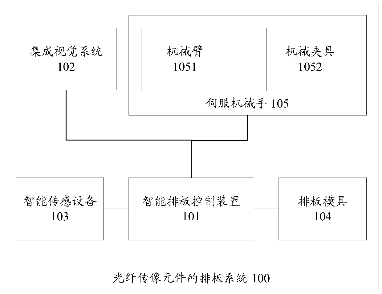
A system for arranging optical fiber imaging components

A technology of optical fiber image transmission and board arrangement, which is applied to optical components, clad optical fibers, optics, etc. Problems such as the component layout system can achieve the effect of improving labor productivity, reducing damage, and reducing production costs

Active Publication Date: 2019-07-19
CHINA BUILDING MATERIALS ACAD
View PDF7 Cites 0 Cited by
  • Summary
  • Abstract
  • Description
  • Claims
  • Application Information

AI Technical Summary

Problems solved by technology

[0003] At present, the key processes of producing optical fiber image transmission components, such as the drawing process of optical fibers and the process of arranging boards, are all done by manual operation, especially the process of arranging boards. Since the diameter of optical fiber filaments is micron Grade, the thickness of the cortex that constitutes the optical fiber filament is as thin as 0.2 microns, and it is extremely easy to be damaged. After the damage, it will seriously affect the light transmission and image transmission performance of the optical fiber, and directly affect the internal image transmission quality of the optical fiber image transmission component.
[0004] Therefore, there is no reasonable board arrangement system for optical fiber image transmission components in the prior art

Method used


Image

  • A system for arranging optical fiber imaging components
  • A system for arranging optical fiber imaging components
  • A system for arranging optical fiber imaging components

Examples


example 1

[0041] Example 1: The intelligent layout control device can pre-store the position information of the standard layout of the optical fiber filament on the preset layout mold, so that after the servo manipulator picks up the optical fiber filament, it can set the position according to the pre-stored layout, Determine the current board status of the fiber optic filament.

example 2

[0042] Example 2: The intelligent board arrangement control device pre-stores the corresponding relationship between the arranged standard optical fiber board section and the board mould, as well as the position information of each wire, so that after the optical fiber wire board is picked up by the servo manipulator, through Query the status information of the fiber optic board section, and confirm the board arrangement status of the fiber optic board section.

[0043] The above S211 to S212 are wire picking steps, the purpose of which is to pick out the unqualified optical fiber wires for size and apparent quality defects of the optical fiber wires used for board arrangement, and record the spatial position information and attribute information of these optical fiber wires . In this way, if there is a pit on the surface of a certain optical fiber filament, if it is prepared into an optical fiber image transmission component, it will seriously affect the internal quality of t...


PUM


Abstract

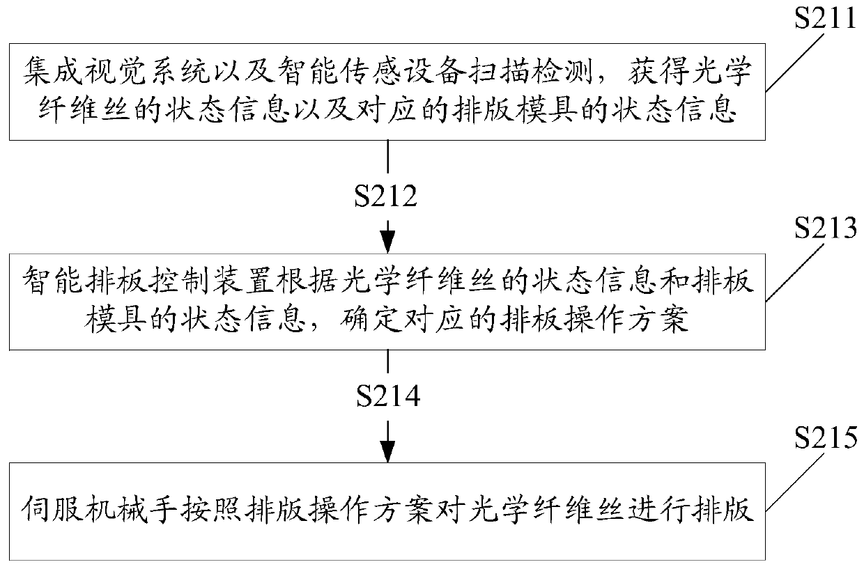
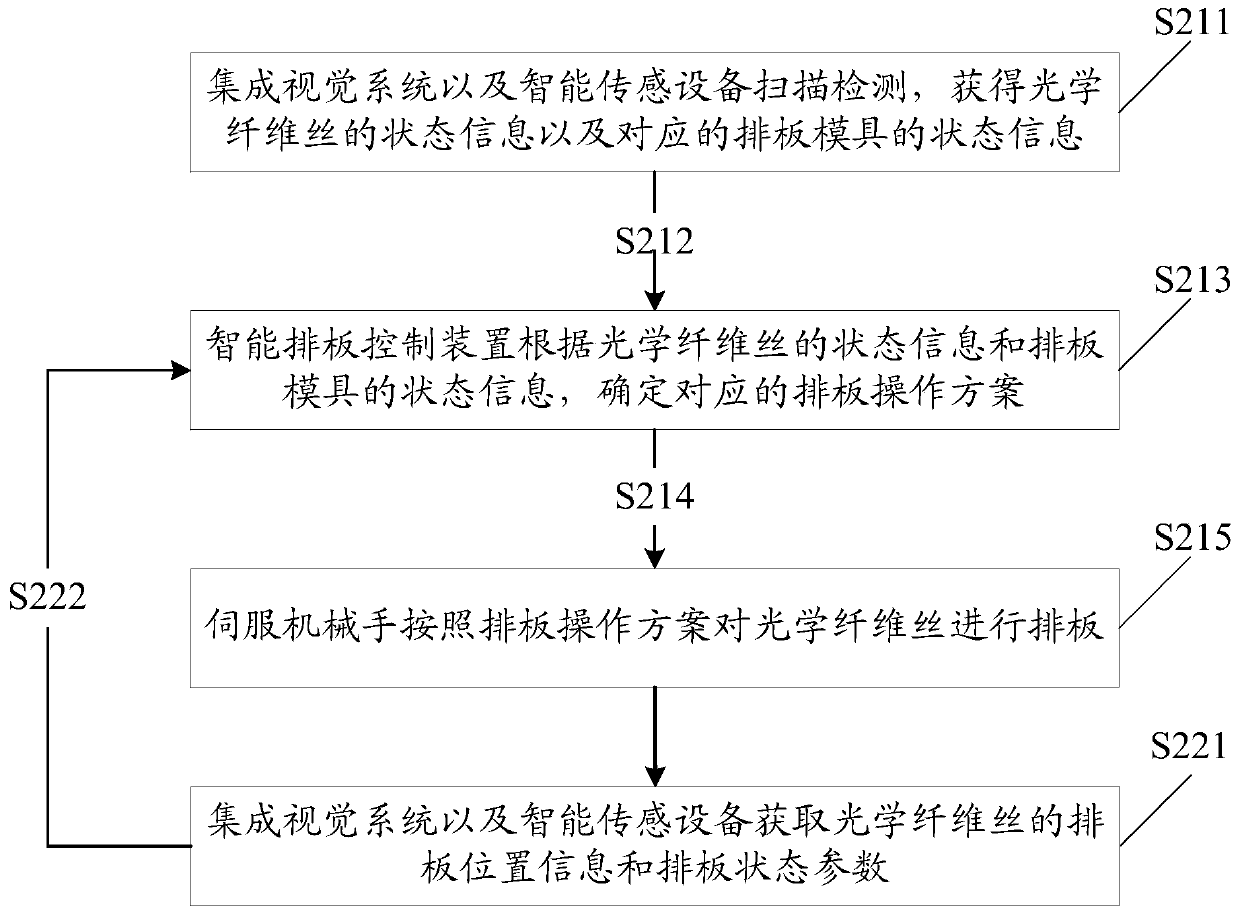
The invention discloses a system for arranging boards of optical fiber image transmission components to realize intelligent board arrangement of optical fiber image transmission components. The system includes: an integrated vision system connected to the intelligent panel control device, intelligent sensing equipment, panel mould, and servo manipulator; the integrated vision system and intelligent sensing equipment are used to scan and detect optical fiber filaments and panel molds , to obtain the state information of the optical fiber filament and the state information of the corresponding panel mould; the intelligent panel control device is used to obtain the state information of the optical fiber filament from the integrated vision system and intelligent sensing equipment and the corresponding information of the optical fiber filament The status information of the layout mold; according to the status information of the optical fiber filament and the status information of the corresponding layout mold, determine the corresponding layout operation plan; send the layout operation plan to the servo manipulator; the servo manipulator is used to follow the board layout Operation plan Carry out board operation for optical fiber filaments.

Description

technical field [0001] The invention relates to the field of manufacturing optical fiber image transmission components, in particular to a board arrangement system for optical fiber image transmission components. Background technique [0002] Optical fiber imaging components, including optical fiber panels, optical fiber inverters, optical fiber cones, optical fiber imaging bundles, and microchannel plates, are photoelectric imaging components with excellent performance, with simple structure, small size, and light weight. , high resolution, large numerical aperture, small inter-stage coupling loss, clear and true image transmission, high light transmission efficiency, optical zero thickness in image transmission, and improved edge image quality. Optical fiber image transmission components are widely used in various cathode ray tubes, camera tubes, charge-coupled device (CCD, Charge-coupled Device) couplings, medical device display screens and high-speed High-definition tel...

Claims


Application Information

Patent Timeline
Patent Type & Authority Patents(China)
IPC IPC(8): G02B7/00G02B6/02
CPCG02B7/00G02B6/02
Inventor 张磊贾金升张弦冯跃冲王三昭汤晓峰许慧超张敬
Owner CHINA BUILDING MATERIALS ACAD
Learn More