Vehicle over-limit detection system and method

A detection system and detection method technology, applied in the field of vehicle overrun detection system, can solve the problems affecting the promotion and engineering application of the system, lack of on-site evidence collection, and difficulty in law enforcement personnel, so as to adapt to harsh natural environments, avoid weighing errors, reduce effect of difficulty

Active Publication Date: 2018-04-20
上海捷崇科技有限公司
View PDF19 Cites 26 Cited by
  • Summary
  • Abstract
  • Description
  • Claims
  • Application Information

AI Technical Summary

Problems solved by technology

However, because the system lacks the function of on-site evidence collection, such as the inability to obtain video information related to overloaded vehicles, it is difficult for law enforcement officers to carry out law enforcement based on limited evidence collection materials, which further affects the promotion and engineering application of the system in the field of intelligent transportation.

Method used


Image

  • Vehicle over-limit detection system and method
  • Vehicle over-limit detection system and method
  • Vehicle over-limit detection system and method

Examples


Embodiment 1

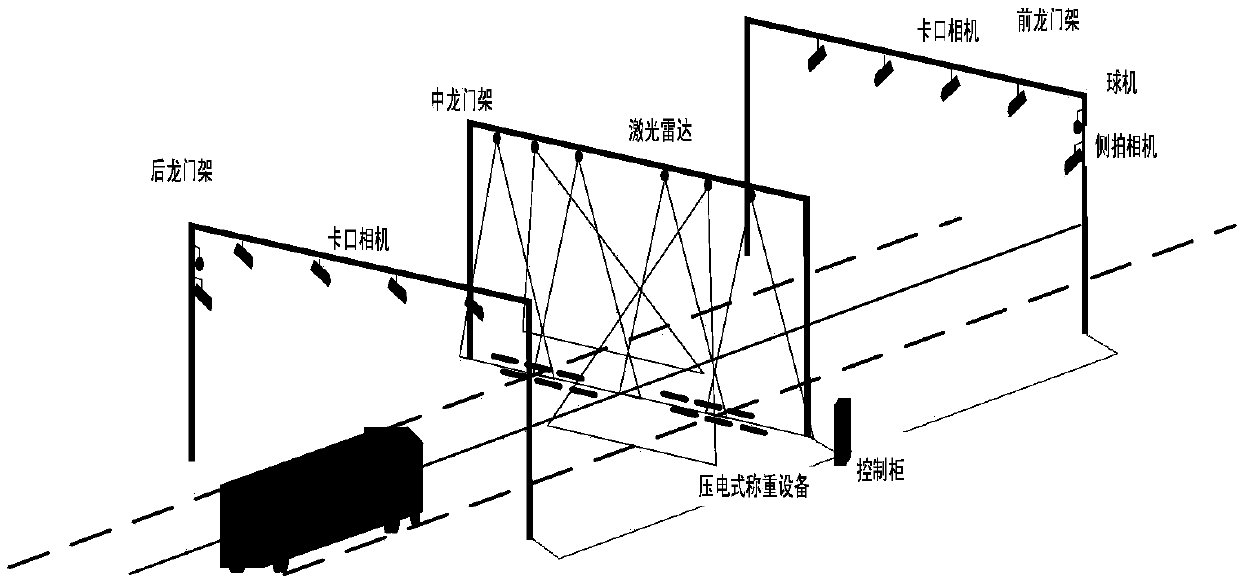
[0033] First introduce the road vehicle overrun detection system of the present embodiment, such as figure 1 As shown, it includes a rear gantry, a middle gantry, and a front gantry arranged sequentially at intervals of one end along the driving direction of the lane. Each of these three gantry frames is about 6 meters high, and the distance between any two is about 20 to 30 meters. Three gantries span N lanes at the same time, and the value of N is determined by the number of lanes to be measured on the highway. The road vehicle overrun detection system also includes a control cabinet, an image acquisition device, a laser scanning device installed on the middle gantry, and a piezoelectric weighing device pre-installed in the driveway. The control cabinet is respectively connected with the image acquisition device, laser scanning device and piezoelectric weighing equipment through LAN or RS485 communication, receives the data information of the communication connection betwee...

Embodiment 2

[0050] For the technical subject of measuring vehicle speed and attributes of length, width and height by laser radar, the second embodiment preferably adopts the following method to calculate the speed of the vehicle driving in the lane on the basis of the first embodiment.

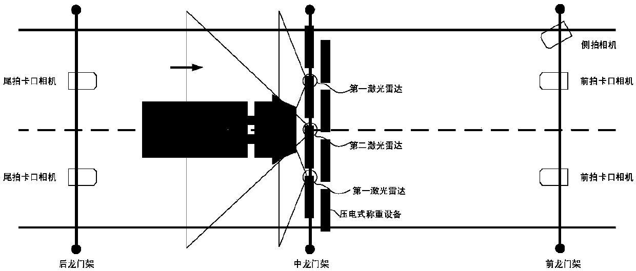
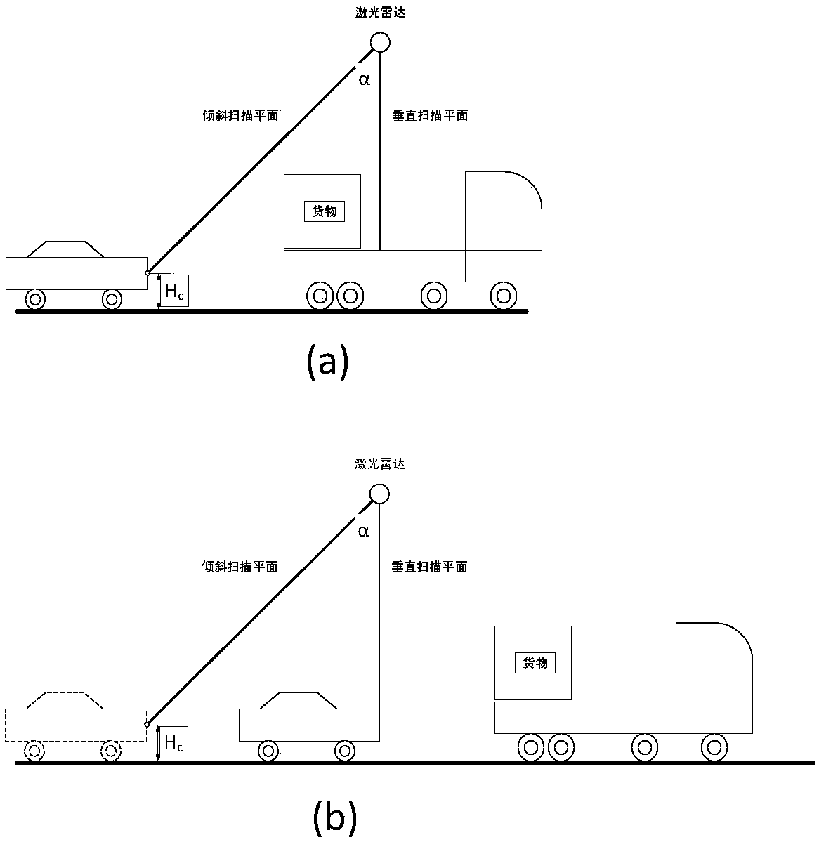
[0051] Such as figure 2 As shown, since the vertical laser plane and the inclined laser plane are close to the ground, it can be approximately considered that the vehicle passes through the two laser planes at a constant speed. Here it is not required that the speeds of the front and rear cars are the same, that is, the distance between two different cars can gradually approach or gradually move away. For the front and rear cars passing through the laser plane process in turn, if there is a situation where the front car blocks the rear car, it often poses greater difficulties and challenges to the measurement of the rear car speed. Obviously, for the inclined scanning plane, if the height of the front ...

Embodiment 3

[0069] Embodiment 3 On the basis of Embodiment 1, the layout of piezoelectric weighing equipment is optimized. Two rows of cross-configured piezoelectric weighing devices are embedded and deployed on the driveway, under the middle gantry and in front of the first laser radar scanning plane. When the wheel is pressed against the surface of the weighing device, a corresponding pressure signal will be generated, and the overall weight of the vehicle can be calculated by processing the pressure signal.

[0070] The reasons for deploying the weighing equipment in the rear row before the intersection of the laser plane and the lane plane are as follows: record the time when the front of the car triggers laser scanning as T1, the time when the front wheels press the weighing equipment is T2, and the time when the rear wheels press the weighing equipment is T2. The moment of heavy equipment is T3, and the moment of the end of laser scanning is T4. Since the wheels are behind the fron...


PUM


Abstract

The invention discloses a vehicle over-limit detection system, and the system comprises a rear portal frame, a central portal frame and a front portal frame, wherein the rear, central and front portalframes are arranged at intervals in the driving direction of a lane. The system also comprises a control cabinet, an image collection device, and a laser scanning device disposed on the central portal frame. The image collection device comprises a tail shooting camera disposed on the rear portal frame, a front shooting camera disposed on the front portal frame, and a side shooting camera disposedon the front portal frame. The control cabinet is connected with the tail shooting camera, the laser scanning device and the front shooting camera in a communication manner, and controls the tail shooting camera, the front shooting camera and the side shooting camera to carry out the image information collection of a vehicle according to the detection information transmitted by the laser scanningdevice. The invention also discloses a detection method for the vehicle over-limit detection system. The system and method provided by the invention can achieve the image and video information collection of the detected vehicle, and provides necessary evidence-obtaining information.

Description

technical field [0001] The invention belongs to the technical field of intelligent transportation, and in particular relates to a vehicle overrun detection system and a detection method thereof. Background technique [0002] Traditional governance is inseparable from the on-site participation of law enforcement officers. For example, when law enforcement officers believe that a vehicle may exceed the limit, guide the vehicle into a specific overtaking control station for final assembly weighing, length, width and height measurement. Due to the low efficiency and high cost of manual law enforcement, the overcrowding effect is poor, and the phenomenon of overloading of road traffic vehicles still occurs frequently, and road traffic accidents caused by this are not uncommon. [0003] Focusing on intelligent and information-based over-limit control, some solutions for intelligent over-limit detection have been gradually proposed at home and abroad. Chinese patent application...

Claims


Application Information

Patent Timeline
Patent Type & Authority Applications(China)
IPC IPC(8): G08G1/017G08G1/04
CPCG08G1/0175G08G1/04
Inventor 孙洁戴冲张欣慰彭楚轩
Owner 上海捷崇科技有限公司
Why Eureka
Try Eureka