
Brushless direct current motor driver

A brushed DC motor and drive technology, which is applied in the control of electromechanical brakes, generator control, motor generator control, etc., can solve problems such as unstable commutation process, high noise decibels, and large torque ripple.

Inactive Publication Date: 2018-04-20
WUHAN NARI LIABILITY OF STATE GRID ELECTRIC POWER RES INST
View PDF4 Cites 2 Cited by
  • Summary
  • Abstract
  • Description
  • Claims
  • Application Information

AI Technical Summary

Problems solved by technology

[0002] The brushless DC control of the existing brushless DC motor driver usually adopts the square wave control method, obtains the position of the rotor through the mechanical sensor, and performs forced commutation at a specific position, resulting in unstable commutation process, large torque ripple, The problem of high noise decibels

Method used


Image

  • Brushless direct current motor driver
  • Brushless direct current motor driver
  • Brushless direct current motor driver

Examples


Embodiment Construction

[0084] In order to make the object, technical solution and advantages of the present invention clearer, the present invention will be further described in detail below in conjunction with the accompanying drawings and embodiments. It should be understood that the specific embodiments described here are only used to explain the present invention, not to limit the present invention.

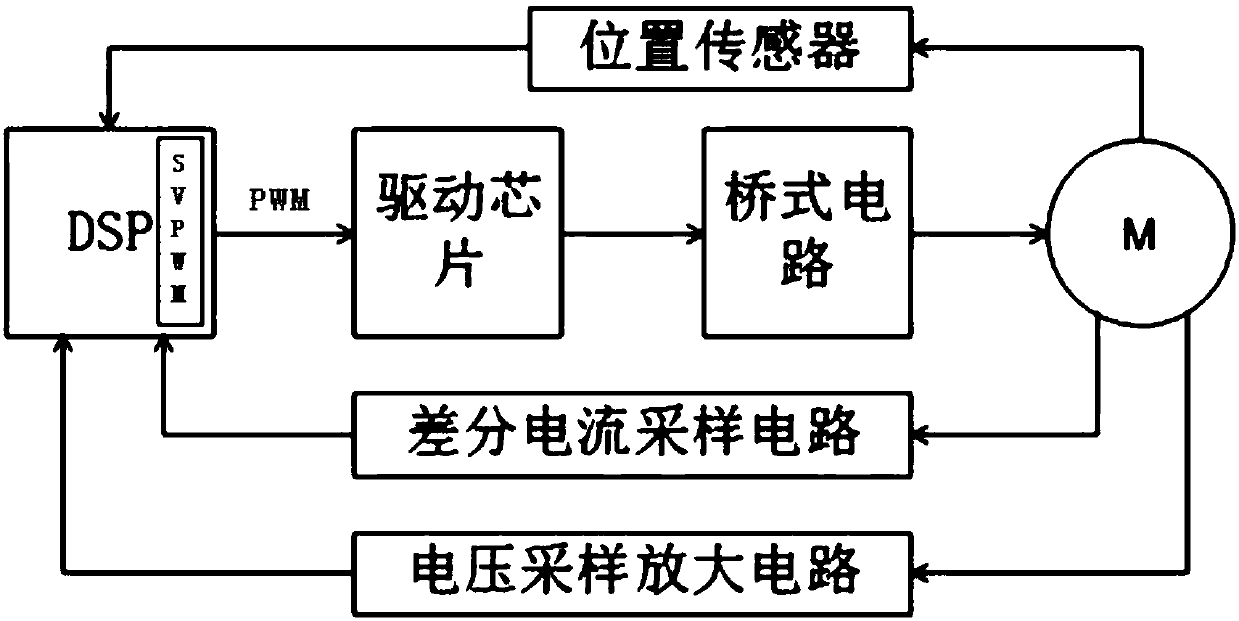
[0085] see Figure 1-Figure 6 , a brushless DC motor driver, which includes a DSP chip, the DSP chip is respectively connected with a position estimation circuit, a space vector pulse width modulator, a differential current sampling circuit, and a voltage acquisition amplifier circuit, and the space vector pulse width modulator , the drive chip, and the bridge circuit are connected in sequence, and the position estimation circuit, the bridge circuit, the differential current sampling circuit, and the voltage sampling amplifying circuit are connected to the motor.

[0086]The bridge circuit is a th...


PUM


Abstract

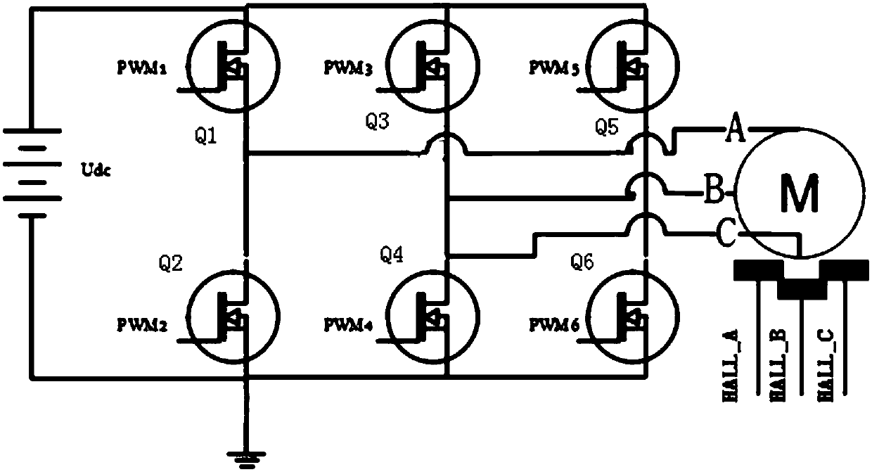
The present invention discloses a brushless direct current motor driver. The brushless direct current motor driver comprises a DSP chip, the DSP chip is connected with a position estimation circuit, adriving chip, a difference current sampling circuit and a voltage collection and amplification circuit, the driving chip is connected with a bridge circuit, and the position estimation circuit, the bridge circuit, the difference current sampling circuit and a voltage sampling and amplification circuit are connected with a motor; the bridge circuit is a three-phase half-bridge circuit and is formed by 6 field effect transistors, each two of the field effect transistors is one half bridge, and one midpoint of each half bridge is connected with one phase of the motor; space vector pulse width modulation is performed in the DSP chip to convert square wave signals to sine wave signals for output; and PWM signals output after space vector pulse width modulation are acted on the three-phase half-bridge circuit through the driving chip and are finally taken as switching signals of the 6 field effect transistors, so as to allow the output current to be a sine wave current. The commutation process is smooth and steady, the noise is small, and the torque ripple is small.

Description

technical field [0001] The invention belongs to the technical field of brushless direct current drive, and in particular relates to a brushless direct current motor driver. Background technique [0002] The brushless DC control of the existing brushless DC motor driver usually adopts the square wave control method, obtains the position of the rotor through the mechanical sensor, and performs forced commutation at a specific position, resulting in unstable commutation process, large torque ripple, The problem of high noise decibels. Contents of the invention [0003] The object of the present invention is to provide a brushless DC motor driver, which has a stable commutation process, low noise and small torque ripple. [0004] The technical scheme adopted in the present invention is: [0005] A brushless DC motor driver, which includes a DSP chip, the DSP chip is respectively connected with a position estimation circuit, a space vector pulse width modulator, a differentia...

Claims


Application Information

Patent Timeline
IPC IPC(8): H02P21/05
CPCH02P21/05
Inventor 王海涛梁文勇王乐希刘辉严碧武冯智慧
Owner WUHAN NARI LIABILITY OF STATE GRID ELECTRIC POWER RES INST
Learn More