Eureka AIR delivers breakthrough ideas for toughest innovation challenges, trusted by R&D personnel around the world.

Two-sided laser welding machine for processing camshafts and processing method thereof

A laser welding machine and processing method technology, applied in laser welding equipment, welding equipment, metal processing equipment and other directions, can solve the problems of high manufacturing cost, long processing process cycle, not meeting the market response speed, etc. Automatically detect positioning, ensure the effect of radial runout detection and follow-up compensation

Active Publication Date: 2018-04-24
WUHAN FARLEYLASERLAB CUTTING SYST ENG
View PDF5 Cites 10 Cited by
  • Summary
  • Abstract
  • Description
  • Claims
  • Application Information

AI Technical Summary

Problems solved by technology

[0004] The purpose of the present invention is to overcome the existing problems of long camshaft processing process cycle, high manufacturing cost, unfavorable development of new products and unsatisfactory market response speed

Method used


Image

  • Two-sided laser welding machine for processing camshafts and processing method thereof
  • Two-sided laser welding machine for processing camshafts and processing method thereof
  • Two-sided laser welding machine for processing camshafts and processing method thereof

Examples


Embodiment Construction

[0033] The following will clearly and completely describe the technical solutions in the embodiments of the present invention with reference to the accompanying drawings in the embodiments of the present invention. Obviously, the described embodiments are only some, not all, embodiments of the present invention. Based on the embodiments of the present invention, all other embodiments obtained by persons of ordinary skill in the art without making creative efforts belong to the protection scope of the present invention.

[0034] In describing the present invention, it is to be understood that the terms "center", "upper", "lower", "front", "rear", "left", "right", "vertical", "horizontal", The orientations or positional relationships indicated by "top", "bottom", "inner", "outer", etc. are based on the orientations or positional relationships shown in the drawings, and are only for the convenience of describing the present invention and simplifying the description, rather than in...


PUM


Abstract

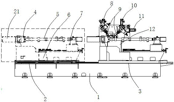
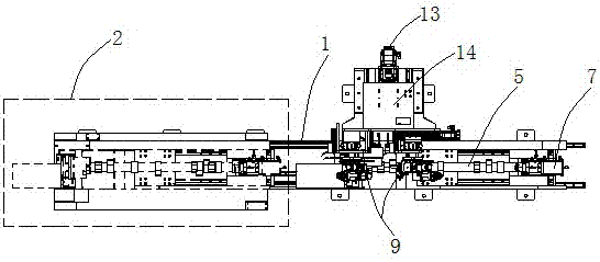
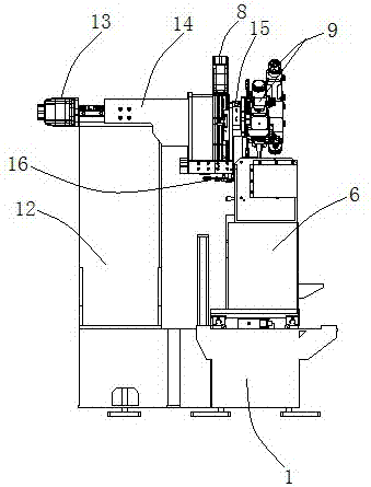
The invention provides a two-sided welding machine for processing camshafts. The two-sided welding machine comprises a base, wherein an X-axis movable worktable is arranged on the base; a fixing mechanism is arranged on the X-axis movable worktable; a main shaft rotating motor is arranged on the fixing mechanism; a vertical pillar is arranged on one side of the base; a Y-axis movable worktable isarranged on the vertical pillar and is connected with a Z1-axis movable worktable and a Z2-axis movable worktable through a Z1 driving mechanism and a Z2 driving mechanism respectively; the Z1-axis movable worktable and the Z2-axis movable worktable are connected with welding joints through angle rotating mechanisms. Through the two-sided welding machine, two welding joints are used for simultaneously and automatically welding two sides of the camshafts, automatically finding welding positions and automatically adjusting Z-axial vertical distance and Y-axial feeding distance between the welding focal points of the welding joints to the axes of the camshafts and included angles between the welding joints and the axes of the camshafts so as to reach the optimum welding position; the existingcamshafts formed by forging or casting are improved into the camshafts formed by welding.

Description

technical field [0001] The invention belongs to the technical field of manufacturing and processing of auto parts, and in particular relates to a double-sided laser welding machine and a processing method for camshaft processing. Background technique [0002] The camshaft is a part of a piston engine that controls the opening and closing of the valves, although in a four-stroke engine the camshaft rotates at half the speed of the crankshaft (in a two-stroke engine the camshaft rotates at the same speed as the crankshaft) , but usually its speed is still very high, and it needs to bear a lot of torque, so the design requires high strength and support for the camshaft. [0003] However, the existing camshaft processing technology still stays at the most basic method of removing metal materials, that is, select the rough shaft material with the largest cam diameter as a reference, or forge a rough blank, and then use the center of the two ends of the shaft to The hole position...

Claims


Application Information

Patent Timeline
IPC IPC(8): B23K26/28B23K26/08B23K26/067
CPCB23K26/067B23K26/0861B23K26/28
Inventor 王鹏叶祖福荣晶吴苶
Owner WUHAN FARLEYLASERLAB CUTTING SYST ENG
Why Eureka
Eureka Blog
Learn More