Special-shaped steel bar, steel bar truss and floor slab hanging mould method system unit

A technology of steel bar trusses and steel bars is applied to the field of steel bars used as upper and lower chord bars of steel bar trusses. Easy, shorten the construction period, and ensure the effect of bearing strength

Inactive Publication Date: 2018-04-24
郭昱良
View PDF13 Cites 1 Cited by
  • Summary
  • Abstract
  • Description
  • Claims
  • Application Information

AI Technical Summary

Problems solved by technology

[0019] As mentioned above, a total of nine steel bars are overlapped with each other on the side, and the resistance welding method is used to fix the connection and assemble to form a steel truss. The strength of the welding points is often uneven, so that its yield strength and bearing capacity are affected by the quality of each welding point. Due to the limitation, it is impossible to give full play to the bearing capacity of the steel truss mechanical design; the resistance welding method is not easy to maintain the consistency of quality in the process of jointing two round rod-shaped objects; therefore, it often requires intensive welding in practical applications. Set up steel trusses, causing waste

Method used


Image

  • Special-shaped steel bar, steel bar truss and floor slab hanging mould method system unit
  • Special-shaped steel bar, steel bar truss and floor slab hanging mould method system unit
  • Special-shaped steel bar, steel bar truss and floor slab hanging mould method system unit

Examples


Embodiment Construction

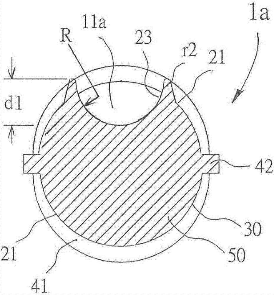
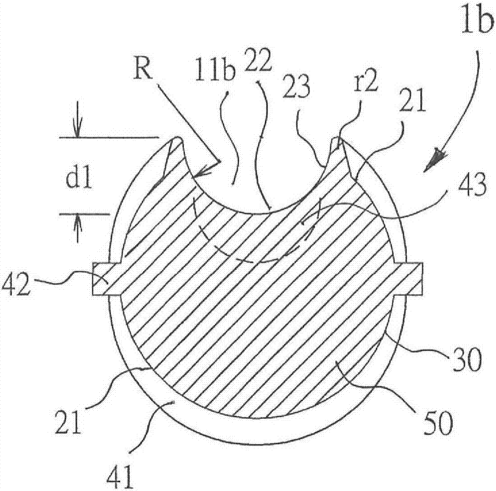
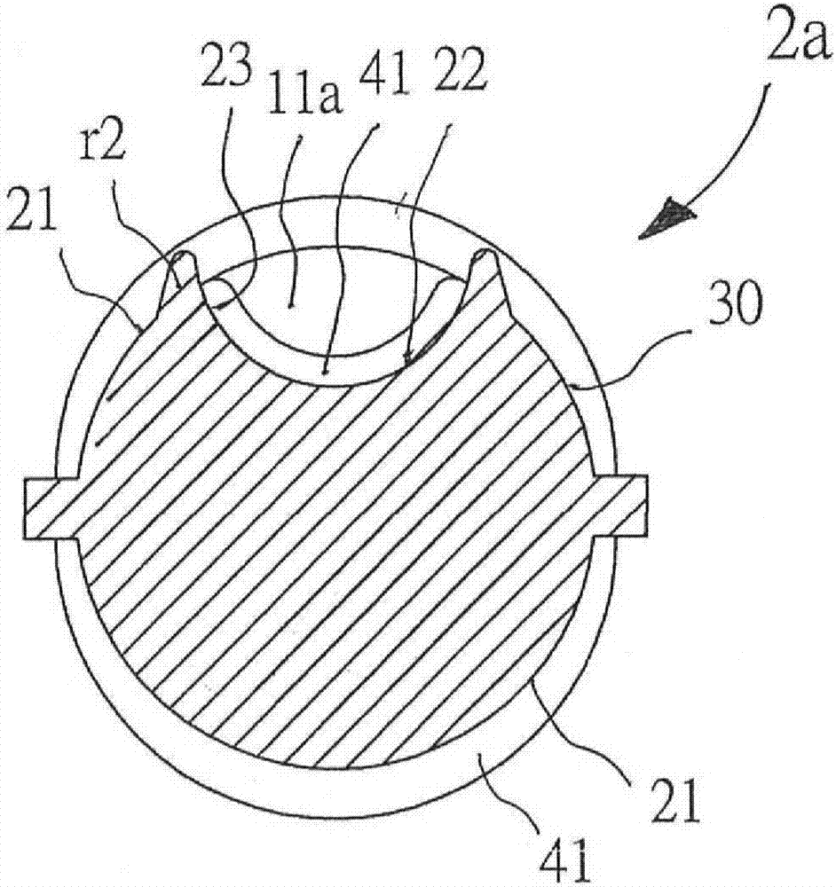
[0133] In order to help your examiner to understand the technical means and technical features used to achieve the purpose of the present invention, as well as the effects that can be achieved by implementing it in the industry, we only express and describe it in detail in the form of embodiments with schematic drawings. Description, and the accompanying drawings used therein are only for illustration and supplementary description purposes, not the actual proportion, number and configuration of steel bars after the actual implementation of the present invention, which will be described in advance.

[0134] For ease of understanding, elements of the same type in the description of the following embodiments are described with the same symbols.

[0135] refer to Figure 6B and Figure 6A , which is a schematic diagram of an embodiment of the special-shaped steel bar of the present invention. in, Figure 6B As shown, with hot rolling and rolling technology, the embodiment of sp...


PUM

PropertyMeasurementUnit
thicknessaaaaaaaaaa

Abstract

The invention provides a special-shaped steel bar, a steel bar truss and a floor slab hanging mould method system unit. The special-shaped steel bar is used as a steel bar for reinforced concrete, inparticular as component materials of upper and lower chord steel bars of the steel bar truss. According to the constitution method, based on the section reduction rate, through hot rolling technology,the special-shaped steel bar having a recessed groove or trench with appropriate width and depth and same cross-sectional shape along the periphery of a long-stripped round steel bard in length direction. The special-shaped steel bar has helical protrusions or recessed lines at regular intervals in the longitudinal direction on the outer peripheral surface of the round steel bar and recessed groove or trench surface. The special-shaped steel bar is assembled with a web steel bar to form a steel bar truss as the basic unit of the steel bar structure of reinforced concrete components. The structural assembly project of steel bars can be simplified and standardized, and the building construction industry of the house can be industrialized. The construction period can be significantly shortened, the construction cost can be reduced, and the consistency of construction quality can be improved.

Description

technical field [0001] The invention relates to a steel bar used as reinforced concrete for construction projects such as civil engineering and house construction, and in particular to a structural material used as the steel bars for the upper and lower chord bars of a steel bar truss. Background technique [0002] Ordinary special-shaped steel bars used in traditional reinforced concrete, such as Figure 15 The hot-rolled ordinary special-shaped steel bars 40 are hot-rolled and rolled to form spiral burls 41 at regular intervals on the outer peripheral surface 21 of the round bar of the steel bar to enhance the bonding force between it and the concrete; During hot rolling, there must be a gap between the upper and lower calender rollers, so that two ribs 42 will be produced in the calendering direction. [0003] The steel structure of the column and beam of the traditional reinforced concrete house building is made of ordinary special-shaped steel bars, and its components a...

Claims


Application Information

Patent Timeline
Patent Type & Authority Applications(China)
IPC IPC(8): E04C5/03E04C5/06E04B5/32
CPCE04B5/32E04C5/03E04C5/0618
Inventor 郭昱良
Owner 郭昱良
Why Eureka
Try Eureka