Method for calibrating central catadioptric camera through three balls at different spatial positions

A technology of spatial position and camera, applied in the field of computer vision, can solve the problem of complex circle point selection

Inactive Publication Date: 2018-04-24
YUNNAN UNIV
View PDF7 Cites 4 Cited by
  • Summary
  • Abstract
  • Description
  • Claims
  • Application Information

AI Technical Summary

Problems solved by technology

However, the selection of the image of the ring point in this document is more complicated

Method used


Image

  • Method for calibrating central catadioptric camera through three balls at different spatial positions
  • Method for calibrating central catadioptric camera through three balls at different spatial positions
  • Method for calibrating central catadioptric camera through three balls at different spatial positions

Examples


Embodiment

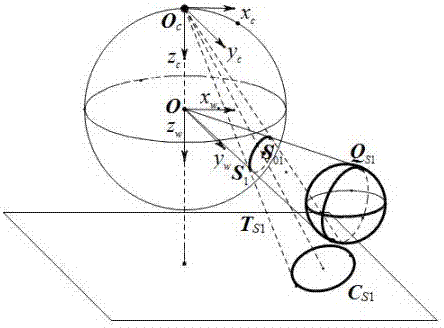
[0094] The present invention proposes a method for linearly solving the internal parameters of the central catadioptric camera using three spheres in space as calibration objects. The schematic diagram of the experimental template structure used in the present invention is as follows figure 1 shown. An embodiment is described in more detail below.

[0095] The template used in the calibration of the central catadioptric camera is three balls with different positions in space, such as figure 1 The ball is Q Si (i=1,2,3), utilize the method of the present invention to calibrate the central catadioptric camera of this experiment, concrete steps are as follows: 1. fitting target curve equation

[0096] The image size used in the present invention is 1700×1600. A central catadioptric camera is used to take an experimental image of the target, read the image, use the Edge function in Matlab to extract the pixel coordinates of the edge points of the image target image, and use t...


PUM


Abstract

The invention discloses a method for calibrating the central catadioptric camera through three balls at different spatial positions, and the method is characterized in that the method just employs theball elements. The method comprises the steps: extracting points on an image from a captured ball image, carrying out the fitting of ball images corresponding to the three balls, and solving the pixels corresponding to the centers of small circles formed by the projection of the three balls on a unit virtual globe; solving a polar line of the circle centers relative to the ball images through therelation between a polar point and the polar line; solving two intersection points of the ball images and the polar line, i.e., the images of circle points; obtaining an absolute conic through the images of the obtained six circle points, finally carrying out the decomposition of the absolute conic, and carrying out the inversion to obtain the internal parameters of the camera.

Description

technical field [0001] The invention belongs to the field of computer vision and relates to a method for solving internal parameters of a central catadioptric camera by using three spheres in space. Background technique [0002] Computer vision refers to the recognition, detection and tracking of targets by simulating human vision through computers, image acquisition and other equipment. The central task of computer vision is to acquire, process, and analyze images. And its ultimate goal is to enable computers to have the ability to recognize the three-dimensional world through two-dimensional images. In visual measurement, the computer obtains two-dimensional image information from the camera to calculate the geometric information of the object in the three-dimensional space, and thus reconstructs and recognizes the object, while the three-dimensional geometric position of the surface point of the space object and the corresponding point in the image The interrelationship...

Claims


Application Information

Patent Timeline
Patent Type & Authority Applications(China)
IPC IPC(8): G06T7/80
CPCG06T2207/20068G06T7/85
Inventor 赵越张敬
Owner YUNNAN UNIV
Why Eureka
Try Eureka