
Intelligent column switch and control system

An on-pillar switch, intelligent technology, applied in information technology support systems, electrical components, sustainable buildings, etc., can solve the problems of heavy and complicated installation and commissioning work, complicated operation of on-pillar switches, prone to errors, etc., to simplify the site. Maintenance workload, reduced probability of error, improved safety effect

Inactive Publication Date: 2018-04-24
国网山东省电力公司蒙阴县供电公司
View PDF2 Cites 1 Cited by
  • Summary
  • Abstract
  • Description
  • Claims
  • Application Information

AI Technical Summary

Problems solved by technology

However, maintenance personnel still need to climb the pole to the control box of the switch on the pole to perform related operations
Moreover, this structure forms many different independent components and accessories such as the switch body, control box, power supply PT, and connecting cables after processing and manufacturing, which makes the installation and debugging work not only heavy and complicated, but also prone to errors, causing equipment damage. Delays in construction lead to loss of power supply
In addition, the operation of this type of pole-mounted switch is more complicated, and it is necessary to ensure that the equipment is effectively grounded, which poses serious safety hazards. Therefore, it is urgent to develop a non-contact, high-safety wireless remote control device that can be easily read The real-time current data of the power grid and various state quantities of the switch on the column can also set the parameters of the switch on the column, and can perform remote opening and closing operations, simplifying the workload of on-site maintenance and minimizing operational safety hazards

Method used


Image

  • Intelligent column switch and control system
  • Intelligent column switch and control system
  • Intelligent column switch and control system

Examples


Embodiment Construction

[0025] In order to make the purpose, technical solutions and advantages of the embodiments of the present invention clearer, the technical solutions in the embodiments of the present invention will be clearly and completely described below in conjunction with the drawings in the embodiments of the present invention. Obviously, the described embodiments It is a part of embodiments of the present invention, but not all embodiments. The components of the embodiments of the invention generally described and illustrated in the figures herein may be arranged and designed in a variety of different configurations.

[0026] Accordingly, the following detailed description of the embodiments of the invention provided in the accompanying drawings is not intended to limit the scope of the claimed invention, but merely represents selected embodiments of the invention. Based on the embodiments of the present invention, all other embodiments obtained by persons of ordinary skill in the art wi...


PUM


Abstract

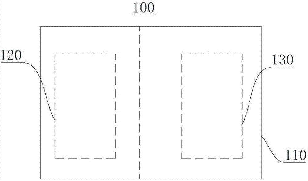
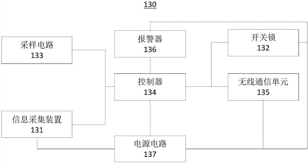
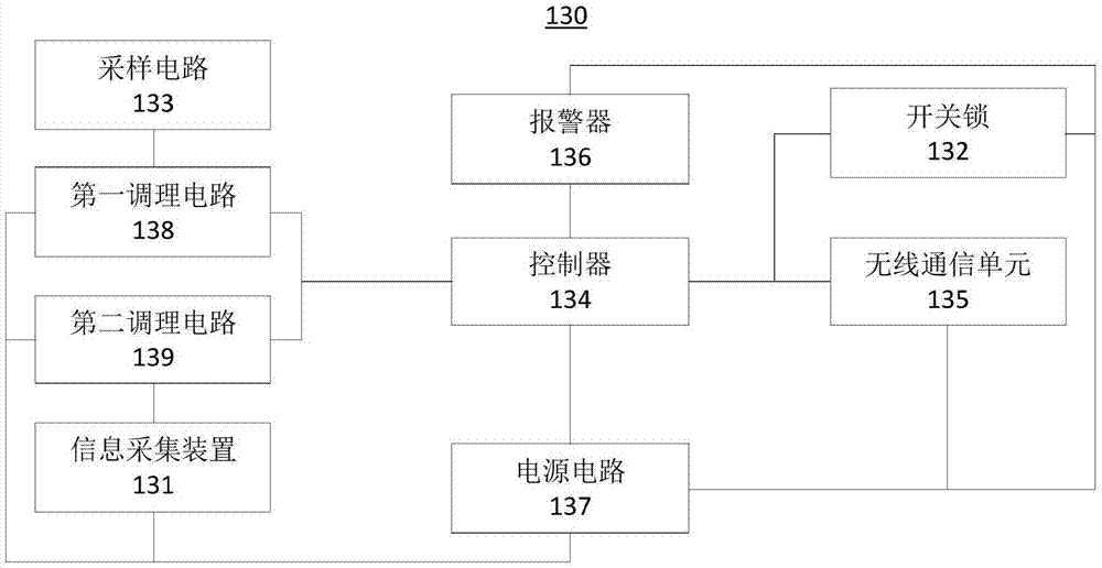
The invention relates to an intelligent column switch and control system, and belongs to the electric power automation technical field; the intelligent column switch comprises a housing, a switch bodyarranged in the housing in an insulated mode, and a control terminal; the control terminal comprises an information acquisition device, a switch lock, a sampling circuit, a power supply circuit, a controller, a wireless communication unit, and an alarm device; the controller is used for preprocessing a wireless signal received from the wireless communication unit, thus obtaining preprocessed information, and determining whether the preprocessed information contains the first information or not; if yes, the first information is coupled with a pre-stored ID information database; if the couplingis finished, operations corresponding to a control order carried by the wireless signal are executed. The intelligent column switch can remotely send the control order according to manager demands, thus opening or closing, adjusting and calibrating parameters, simplifying field maintenance work load, and maximumly reducing the operation safety troubles.

Description

technical field [0001] The invention belongs to the technical field of electric power automation, and in particular relates to an intelligent pole-mounted switch and a control system. Background technique [0002] In the domestic distribution network, a certain number of pole-mounted switches are installed on the overhead line. In the routine maintenance process, the traditional switch on the pole requires the maintenance personnel to climb the pole to the switch on the pole to open and close the switch. For the current intelligent pole switch, although it is equipped with a control box, considering the convenience and safety of local operation, the control box is generally far away from the installation position of the switch. The power supply of the control box is also connected to the control box by one or two voltage transformers through cables to realize power supply and voltage data collection. However, maintenance personnel still need to climb the pole to the contro...

Claims


Application Information

Patent Timeline
Patent Type & Authority Applications(China)
IPC IPC(8): H02J13/00
CPCH02J13/0075Y02B90/20Y04S40/126
Inventor 孙云才石立行王磊丁蕾吕承伟公志国宋晓庆
Owner 国网山东省电力公司蒙阴县供电公司
Learn More