Hot-melting welding device of plastic composite pipe of steel wire framework

A hot-melt welding, steel wire skeleton technology, applied in the direction of tubular items, other household appliances, household appliances, etc., can solve the problems of asymmetric axial pressure, slow progress, uneven heating, etc., to save time, tight contact, Economical effect

Pending Publication Date: 2018-04-27
HARBIN JIANCHENG GRP
View PDF3 Cites 2 Cited by
  • Summary
  • Abstract
  • Description
  • Claims
  • Application Information

AI Technical Summary

Problems solved by technology

[0003] The present invention aims to solve the problems of asymmetrical axial pressure on the pipe, uneven heating, and progress in batch operation in the butt welding process of the existing butt welding tools used in the manual hot-melt welding of steel wire skeleton plastic composite pipes. slow problem, and then provides a steel wire skeleton plastic composite pipe thermal fusion welding device

Method used


Image

  • Hot-melting welding device of plastic composite pipe of steel wire framework
  • Hot-melting welding device of plastic composite pipe of steel wire framework
  • Hot-melting welding device of plastic composite pipe of steel wire framework

Examples


specific Embodiment approach 1

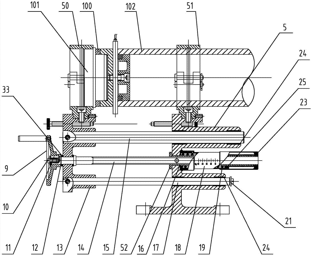
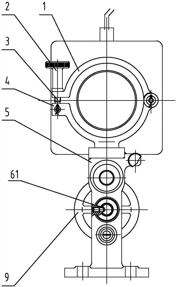
[0021] Specific implementation mode one: combine Figure 1 to Figure 4 Description of this embodiment, a steel wire skeleton plastic composite pipe hot-melt welding device, which includes a moving assembly, a clamping assembly and a heating device, the moving assembly includes a guide body 5, a moving body 13, a handle 9, a screw sleeve 16, a scale The pipe 18, the pipe cover 23, the lead screw 14 and two guide rods arranged horizontally respectively, the guide body 5 and the moving body 13 are arranged vertically and juxtaposed from left to right, wherein the lower part of the guide body 5 is horizontally fixed on the working table , the screw sleeve 16 is mounted on the guide body 5, and the screw sleeve 16 is limited in the circumferential direction by the screw fixed on the guide body 5. The screw 14 is worn on the moving body 13 and the screw sleeve in turn from left to right. 16, threaded connection between the screw sleeve 16 and the lead screw 14, the lead screw 14 is ...

specific Embodiment approach 2

[0028] Specific implementation mode two: combination figure 1 To illustrate this embodiment, the screw sleeve 16 is in clearance fit with the guide body 5 , and the left end of the screw sleeve 16 is fixedly connected to the limiting ring 52 . Designed in this way, the clearance fit between the screw sleeve 16 and the guide body 5 facilitates the movement of the screw sleeve 16 in the guide body 5, and the limit ring 52 limits the limit displacement of the screw sleeve 16 to the right, preventing the screw sleeve 16 from moving due to the action of the spring 19. Detach guide body 5. Other compositions and connections are the same as those in the first embodiment.

specific Embodiment approach 3

[0029] Specific implementation mode three: combination figure 1 , 2Describe this embodiment, two guide rods are first guide rod 15 and second guide rod 17 respectively, and first guide rod 15 is positioned at the top of lead screw 14, and second guide rod 17 is positioned at the bottom of lead screw 14, two guide rods The left ends of the rods are respectively worn on the mobile body 13 and are fixedly connected with the mobile body 13 . In such a design, the guide rod will guide the moving body 13, and at the same time support the moving part and the mold 101. Therefore, the left end of the guide rod is installed in the moving body 13 to increase the distance between the guide rod and the moving body 13. connection stability, even if the connection between the guide rod and the moving body 13 is stronger. Other compositions and connections are the same as those in Embodiment 1 or Embodiment 2.


PUM


Abstract

The invention discloses a hot-melting welding device of a plastic composite pipe of a steel wire framework, and belongs to the technical field of comprehensive machining. The hot-melting welding device solves the problems that at present, in a butt welding tool adopted when manual hot-melting welding is carried out on a plastic composite pipe of a steel wire framework, in the butt welding process,the axial application pressure to the pipe is not symmetric, heating is not uniform, and the schedule during batch operation treatment is slow. A lead screw is sequentially mounted on a moving body and a screw sleeve in a penetrating manner. The lead screw is rotationally and fixedly connected to the moving body. The left ends of two guide rods are fixedly connected to the moving body. The rightends of the two guide rods are mounted in a guide body in a penetrating manner. A graduated pipe is mounted on the screw sleeve in a sleeved manner. A spring is arranged between the graduated pipe andthe screw sleeve. A pipe cover is mounted on the screw sleeve in a sleeving manner. The right end of the graduated pipe is located between the screw sleeve and the pipe cover. A jig is fixed above the moving body through a first clamp ring, and a second clamp ring provided with a pipeline in a penetrating manner is fixed above the guide body. A heating device is arranged between a pipe head and the pipeline. The hot-melting welding device is used for hot-melting welding of the plastic composite pipe of the steel wire framework.

Description

technical field [0001] The invention relates to a hot-melt welding device, in particular to a steel wire frame plastic composite pipe hot-melt welding device, which belongs to the technical field of comprehensive processing. Background technique [0002] High-density steel wire skeleton polyethylene plastic composite pipes (steel mesh skeleton interlayer in the middle of the pipe wall), the pipeline needs to be cut on site during the construction process, and the steel wire skeleton will be exposed on the end surface of the cut pipeline, which needs to be sealed by hot-melt welding The exposed wire skeleton. In the hot-melt welding process, plastic pipe heads of the same diameter and size (without metal mesh interlayer in the pipe wall) are used to butt-weld them. This processing method only uses simple butt welding tools when manual hot-melt welding is used, manual operation during butt welding, uneven heating, asymmetric axial pressure on the pipe during the butt welding ...

Claims


Application Information

Patent Timeline
Patent Type & Authority Applications(China)
IPC IPC(8): B29C65/20B29C65/78B29L23/00
CPCB29C65/20B29C65/7841B29C66/5221B29L2023/22
Inventor 李新仲昭明丁学彬
Owner HARBIN JIANCHENG GRP
Why Eureka
Try Eureka