Opposite irradiation type photoelectric sensor and target detection system

A photoelectric sensor and target detection technology, applied in the field of photoelectric sensors, can solve the problems of optical axis deviation, difficult alignment of light emitter and light receiver, and narrow installation space, achieve small installation spacing, overcome W/B shadows, and ensure consistency sexual effect

Inactive Publication Date: 2018-04-27
ORMON CORP
View PDF0 Cites 1 Cited by
  • Summary
  • Abstract
  • Description
  • Claims
  • Application Information

AI Technical Summary

Problems solved by technology

[0005] However, at present, due to the very narrow installation space in the thin gate, the installation bracket that can adjust the angle of the light receiver cannot be installed; and, if the design simply reduces the field of view, the optical axis of the light emitter and light receiver will be different during installation. Alignment is very difficult
[0006] In addition, when installing the light emitter and light receiver, it is necessary to align the optical axis of the light receiver with the optical axis of the light emitter, but due to the influence of LED component deviation and / or installation deviation and / or printed circuit board (PWB) assembly deviation, etc. The optical axis is shifted, so that the center of the spot is displaced relative to the mechanical axis, and the optical receiver may have a certain offset in the direction perpendicular to the optical axis (that is, the optical receiver has a translation distance relative to the optical axis), which will affect the parallelism. mobile features

Method used


Image

  • Opposite irradiation type photoelectric sensor and target detection system
  • Opposite irradiation type photoelectric sensor and target detection system
  • Opposite irradiation type photoelectric sensor and target detection system

Examples


Embodiment 1

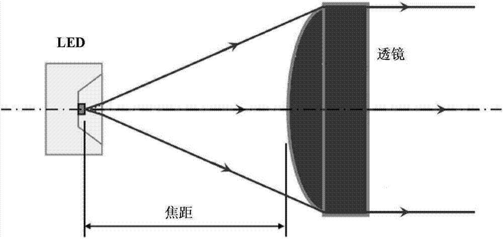
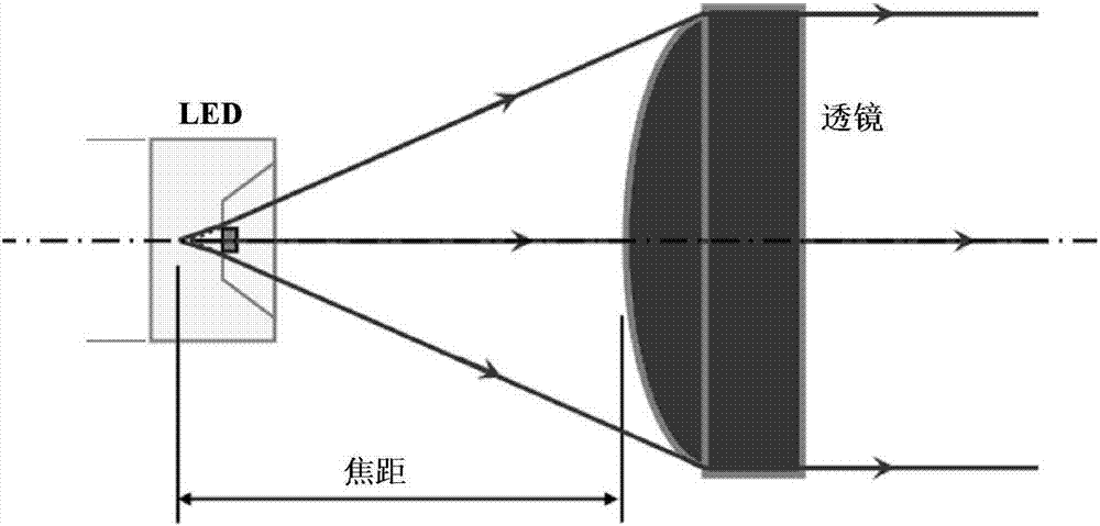
[0046] Embodiment 1 of the present invention provides a through-beam photoelectric sensor, Figure 5 It is a structural schematic diagram of the through-beam photoelectric sensor of Embodiment 1 of the present invention. Such as Figure 5 As shown, the through-beam photoelectric sensor 50 includes a light projector 51 and a light receiver 52 . Figure 6 It is a schematic diagram of the light path on the emitter side.

[0047] Such as Figure 5 and 6 As shown, the light projector 51 may include: a light emitting element 511 , a first lens 512 , and a first baffle 513 .

[0048]The light emitting element 511 emits light. The first lens 512 converts the light emitted by the light emitting element 511 into parallel light. The first baffle 513 is located between the light-emitting element 511 and the first lens 512, and a first through hole 5131 is provided on the first baffle 513. The center of the first through hole 5131 coincides with the focal point of the first lens 512....

Embodiment 2

[0068] Embodiment 2 of the present invention provides a target detection system, which has a plurality of through-beam photoelectric sensors described in embodiment 1. Since the through-beam photoelectric sensor has been described in embodiment 1, Its content is incorporated here, and will not be repeated here.

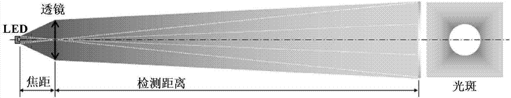
[0069] In this embodiment, the target detection system can detect whether there is a target (pedestrian or object) passing through the plurality of through-beam photoelectric sensors. In one embodiment, the target detection system can be applied to subway gates.

[0070] In this embodiment, the distance between every two through-beam photoelectric sensors may be less than or equal to 80 millimeters, so as to meet the requirements of parallel movement characteristics.

[0071] In this embodiment, all the projectors of the multiple through-beam photoelectric sensors can be installed on one side of the gate, and all the light receivers of the multiple through-beam photo...


PUM


Abstract

The embodiment of the invention relates to an opposite irradiation type photoelectric sensor and a target detection system. The opposite irradiation type photoelectric sensor comprises a light projector and light receiver, wherein the light projector comprises a light emitting element, a first lens, a first baffle plate, the light emitting element emits light, the first lens converts the light emitted by the light emitting element into parallel light, the first baffle plate is located between the light emitting element and the first lens, the first baffle plate is provided with a first throughhole, the center of the first through hole is overlapped with the focus of the first lens, and the field of view formed by the light emitted from the light emitting element is controlled through thefirst through hole. According to the embodiment of the invention, a sufficient-light light spot of a required shape can be obtained, a small installation distance between the opposite irradiation typephotoelectric sensors can be met, and the consistency of optical axes can also be ensured.

Description

technical field [0001] The invention relates to a photoelectric sensor, in particular to a through-beam photoelectric sensor and a target detection system using the through-beam photoelectric sensor. Background technique [0002] In the prior art, the focal point of the lens in the light projector in the through-beam photoelectric sensor is usually set at the light source, for example, the LED chip, such as figure 1 shown. However, since the metal wire connection part (W / B, Wire Bonding) of the wafer on the LED chip does not emit light, the amount of light projected into the center of the light spot in the light receiver will not be sufficient, and there will be W / B shadow effects, such as figure 2 As shown, it is easy to misjudgment when using the through-beam photoelectric sensor to detect whether there is a target. [0003] In order to solve the above problems, the LED chip can be moved to the direction of the lens in the light projector to become a defocused state, su...

Claims


Application Information

Patent Timeline
Patent Type & Authority Applications(China)
IPC IPC(8): G01V8/12
CPCG01V8/12G01J1/0437G01J1/08G01J1/0266G01J1/0411G01J1/4228G01J1/44
Inventor 李国培杨雪施霁朱明奥浓基晴
Owner ORMON CORP
Why Eureka
Try Eureka